
Datasheet

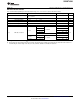


C
L
= 50 pF
500
500
7 V
S1From Ouput
Under Test
V
OH
Input
Output
V
OL
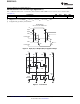
1.5 V1.5 V
1.5 V1.5 V
3 V
0 V
t
PLH
t
PHL
AC Waveforms
SN74GTL2003
www.ti.com
SCDS305A –FEBRUARY 2011–REVISED MARCH 2013
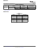
AC Characteristics for Translator-Type Applications
GND = 0 V, t
R
, C
L
= 50 pF, G
REF
= 5 V ± 0.5 V, T
amb
= –40°C to 85°C
PARAMETER MIN MAX UNIT
t
pd
Propagation delay
(1)
250 ps
(1) This parameter is warranted but not production tested. The propagation delay is based on the RC time constant of the typical on-state
resistance of the switch and a load capacitance of 50 pF, when driven by an ideal voltage source (zero output impedance).
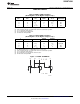
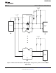
Figure 4. Input (Sn) to Output (Dn) Propagation Delays
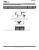
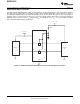
Figure 5. Load Circuit
Test S1
t
pd
Open
t
PLZ
/t
PZL
7 V
T
PHZ
/T
PZH
Open
C
L
= Load Capacitance, includes jig and probe capacitance (See AC Characteristics for value)
Copyright © 2011–2013, Texas Instruments Incorporated Submit Documentation Feedback 7
Product Folder Links: SN74GTL2003