
Datasheet


( )
( )
Pullup voltage V 0.35 V
Resistor value
0.015 A
-
W =
SN74GTL2003
SCDS305A –FEBRUARY 2011–REVISED MARCH 2013
www.ti.com
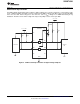
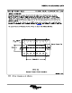
Sizing Pullup Resistors
The pullup resistor value should limit the current through the pass transistor when it is in the on state to about 15
mA. This ensures a pass voltage of 260 mV to 350 mV. If the current through the pass transistor is higher than
15 mA, the pass voltage also is higher in the on state. To set the current through each pass transistor at 15 mA,
the pullup resistor value is calculated as:
(1)
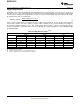
Table 4 shows resistor values for various reference voltages and currents at 15 mA, 10 mA, and 3 mA. The
resistor value shown in the +10% column, or a larger value, should be used to ensure that the pass voltage of
the transistor would be 350 mV or less. The external driver must be able to sink the total current from the
resistors on both sides of the GTL device at 0.175 V, although the 15 mA only applies to current flowing through
the SN74GTL2003.
Table 4. Pullup Resistor Values
(1)(2)(3)
PULLUP RESISTOR VALUE (Ω)
15 mA 10 mA 3 mA
VOLTAGE
NOMINAL +10% NOMINAL +10% NOMINAL +10%
5.0 V 310 341 465 512 1550 1705
3.3 V 197 217 295 325 983 1082
2.5 V 143 158 215 237 717 788
1.8 V 97 106 145 160 483 532
1.5 V 77 85 115 127 383 422
1.2 V 57 63 85 94 283 312
(1) Calculated for V
OL
= 0.35 V
(2) Assumes output driver V
OL
= 0.175 V at stated current
(3) +10% to compensate for V
DD
range and resistor tolerance
12 Submit Documentation Feedback Copyright © 2011–2013, Texas Instruments Incorporated
Product Folder Links: SN74GTL2003