
Datasheet

www.ti.com
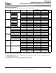
Electrical Characteristics
(1) (2)
(Continued)
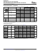
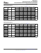
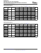
Switching Characteristics
SN74AVCH1T45
SINGLE-BIT DUAL-SUPPLY BUS TRANSCEIVER
WITH CONFIGURABLE VOLTAGE TRANSLATION AND 3-STATE OUTPUTS
SCES598D – JULY 2004 – REVISED JANUARY 2008
over recommended operating free-air temperature range (unless otherwise noted)
T
A
= 25 ° C – 40 ° C to 85 ° C
PARAMETER TEST CONDITIONS V
CCA
V
CCB
UNIT
MIN TYP MAX MIN MAX
A port 0 V 0 to 3.6 V ± 0.1 ± 1 ± 5
I
off
V
I
or V
O
= 0 to 3.6 V µ A
B port 0 to 3.6 V 0 V ± 0.1 ± 1 ± 5
B port 0 V 3.6 V ± 0.5 ± 2.5 5
V
O
= V
CCO
or GND,
I
OZ
µ A
V
I
= V
CCI
or GND
A port 3.6 V 0 V ± 0.5 ± 2.5 5
1.2 V to 3.6 V 1.2 V to 3.6 V 10
I
CCA
V
I
= V
CCI
or GND, I
O
= 0 0 V 3.6 V – 2 µ A
3.6 V 0 V 10
1.2 V to 3.6 V 1.2 V to 3.6 V 10
I
CCB
V
I
= V
CCI
or GND, I
O
= 0 0 V 3.6 V 10 µ A
3.6 V 0 V – 2
I
CCA
+ I
CCB
V
I
= V
CCI
or GND, I
O
= 0 1.2 V to 3.6 V 1.2 V to 3.6 V 20 µ A
Control
C
i
V
I
= 3.3 V or GND 3.3 V 3.3 V 2.5 pF
inputs
A or B
C
io
V
O
= 3.3 V or GND 3.3 V 3.3 V 6 pF
port
(1) V
CCO
is the V
CC
associated with the output port.
(2) V
CCI
is the V
CC
associated with the input port.
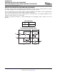
over recommended operating free-air temperature range, V
CCA
= 1.2 V (see Figure 11 )
V
CCB
= 1.2 V V
CCB
= 1.5 V V
CCB
= 1.8 V V
CCB
= 2.5 V V
CCB
= 3.3 V
FROM TO
PARAMETER UNIT
(INPUT) (OUTPUT)
TYP TYP TYP TYP TYP
t
PLH
3.3 2.7 2.4 2.3 2.4
A B ns
t
PHL
3.3 2.7 2.4 2.3 2.4
t
PLH
3.3 3.1 2.9 2.8 2.7
B A ns
t
PHL
3.3 3.1 2.9 2.8 2.7
t
PHZ
5.1 5.2 5.3 5.2 3.7
DIR A ns
t
PLZ
5.1 5.2 5.3 5.2 3.7
t
PHZ
5.3 4.3 4 3.3 3.7
DIR B ns
t
PLZ
5.3 4.3 4 3.3 3.7
t
PZH
(1)
8.5 6.9 6.4 5.5 6.1
DIR A ns
t
PZL
(1)
8.5 6.9 6.4 5.5 6.1
t
PZH
(1)
8.3 7.8 7.7 7.5 5.9
DIR B ns
t
PZL
(1)
8.3 7.8 7.7 7.5 5.9
(1) The enable time is a calculated value, derived using the formula shown in the enable times section.
6 Submit Documentation Feedback Copyright © 2004 – 2008, Texas Instruments Incorporated
Product Folder Link(s): SN74AVCH1T45