
Datasheet


SGLS128A − JULY 2002 − REVISED APRIL 2008
7
POST OFFICE BOX 655303 • DALLAS, TEXAS 75265
PARAMETER MEASUREMENT INFORMATION
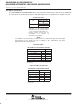
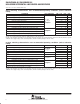
driver
V
OD
V
OZ
V
OY
V
OC
V
I
I
OY
I
OZ
I
I
A
Z
Y
V
OY
) V
OZ
2
Driver Enable
Figure 1. Driver Voltage and Current Definitions
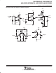
2 V
1.4 V
0.8 V
100%
80%
20%
0%
0 V
V
OD(H)
V
OD(L)
Output
Input
t
PHL
t
PLH
t
f
t
r
_
+
V
OD
50 Ω
3.75 kΩ
3.75 kΩ
0 ≤ V
test
≤ 2.4 V
Y
Z
DA
Input
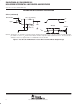
NOTE A: All input pulses are supplied by a generator having the following characteristics: t
r
or t
f
≤ 1 ns, pulse repetition rate (PRR) = 50 Mpps,
pulse width = 10 ± 0.2 ns . C
L
includes instrumentation and fixture capacitance within 0,06 mm of the D.U.T.
Figure 2. Test Circuit, Timing, and Voltage Definitions for the Differential Output Signal