
Datasheet


SGLS128A − JULY 2002 − REVISED APRIL 2008
6
POST OFFICE BOX 655303 • DALLAS, TEXAS 75265
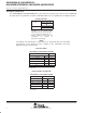
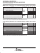
driver switching characteristics over recommended operating conditions (unless otherwise
noted)
PARAMETER TEST CONDITIONS MIN TYP
†
MAX UNIT
t
PLH
Propagation delay time, low-to-high-level output 1.7 3 ns
t
PHL
Propagation delay time, high-to-low-level output 1.7 3 ns
t
r
Differential output signal rise time
R
L
= 50Ω,
0.6 1.2 ns
t
f
Differential output signal fall time
R
L
= 50Ω,
C
L
= 10 pF,
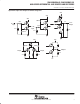
See Figure 5
0.6 1.2 ns
t
sk(p)
Pulse skew (|t
pHL
− t
pLH
|)
C
L
= 10 pF,
See Figure 5
750 ps
t
sk(o)
Channel-to-channel output skew
‡
100 ps
t
sk(pp)
Part-to-part skew
§
1 ns
t
PZH
Propagation delay time, high-impedance-to-high-level output 6 10 ns
t
PZL
Propagation delay time, high-impedance-to-low-level output
See Figure 6
6 10 ns
t
PHZ
Propagation delay time, high-level-to-high-impedance output
See Figure 6
4 10 ns
t
PLZ
Propagation delay time, low-level-to-high-impedance output 5 10 ns
†
All typical values are at 25°C and with a 3.3-V supply.
‡
t
sk(o)
is the maximum delay time difference between drivers on the same device.
§
t
sk(pp)
is the magnitude of the difference in propagation delay times between any specified terminals of two devices when both devices operate
with the same supply voltages, at the same temperature, and have identical packages and test circuits.
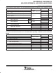
receiver switching characteristics over recommended operating conditions (unless otherwise
noted)
PARAMETER TEST CONDITIONS MIN TYP
†
MAX UNIT
t
PLH
Propagation delay time, low-to-high-level output
C
L
= 10 pF,
3.7 4.5 ns
t
PHL
Propagation delay time, high-to-low-level output
C
L
= 10 pF,
See Figure 7
3.7 4.5 ns
t
sk(p)
Pulse skew (|t
pHL
− t
pLH
|)
See Figure 7
0.1 ns
t
sk(o)
Channel-to-channel output skew 0.2 ns
t
sk(pp)
Part-to-part skew
‡
1 ns
t
r
Output signal rise time
C
L
= 10 pF,
0.7 1.5 ns
t
f
Output signal fall time
C
L
= 10 pF,
See Figure 7
0.9 1.5 ns
t
PZH
Propagation delay time, high-level-to-high-impedance output 2.5 ns
t
PZL
Propagation delay time, low-level-to-low-impedance output
See Figure 8
2.5 ns
t
PHZ
Propagation delay time, high-impedance-to-high-level output
See Figure 8
7 ns
t
PLZ
Propagation delay time, low-impedance-to-high-level output 4 ns
†
All typical values are at 25°C and with a 3.3-V supply.
‡
t
sk(pp)
is the magnitude of the difference in propagation delay times between any specified terminals of two devices when both devices operate
with the same supply voltages, at the same temperature, and have identical packages and test circuits.