
Car Stereo System - Car Radio Digital Signal Processor User Manual


www.ti.com
SM320C6455-EP
FIXED-POINT DIGITAL SIGNAL PROCESSOR
SPRS462B – SEPTEMBER 2007 – REVISED JANUARY 2008
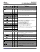
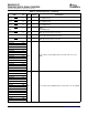
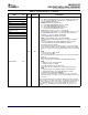
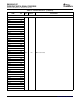
Table 2-3. Terminal Functions (continued)
SIGNAL
TYPE
(1)
IPD/IPU
(2)
DESCRIPTION
NAME NO.
AEA10/MACSEL1 M25
• EMAC/MDIO interface select bits (MACSEL[1:0])
If the EMAC and MDIO peripherals are enabled, AEA12 pin (UTOPIA_EN
AEA9/MACSEL0 M27
= 0) , there are two additional configuration pins — MACSEL[1:0] — to
AEA8/PCI_EEAI P25
select the EMAC/MDIO interface.
AEA[10:9]: MACSEL[1:0] with AEA12 =0.
AEA7 N27
00 - 10/100 EMAC/MDIO MII Mode Interface (default)
AEA6/PCI66 U27
01 - 10/100 EMAC/MDIO RMII Mode Interface
AEA5/MCBSP1_EN U28
10 - 10/100/1000 EMAC/MDIO GMII Mode Interface
11 - 10/100/1000 with RGMII Mode Interface
AEA4/
T28
SYSCLKOUT_EN [RGMII interface requires a 1.8 V or 1.5 V I/O supply]
When UTOPIA is enabled (AEA12 = 1), if the MACSEL[1:0] bits = 11 then,
AEA3 T27
the EMAC/MDIO RGMII interface is still functional. For more detailed
AEA2/CFGGP2 T26
information, see Section 3 , Device Configuration.
AEA1/CFGGP1 U26
• PCI I2C EEPROM Auto-Initialization (PCI_EEAI)
AEA8: PCI auto-initialization via external I2C EEPROM
If the PCI peripheral is disabled (PCI_EN pin = 0), this pin must not be
pulled up.
0 - PCI auto-initialization through I2C EEPROM is disabled (default).
1 - PCI auto-initialization through I2C EEPROM is enabled.
• PCI Frequency Selection (PCI66)
[The PCI peripheral needs be enabled (PCI_EN = 1) to use this function]
Selects the PCI operating frequency of 66 MHz or 33 MHz PCI operating
frequency is selected at reset via the pullup/pulldown resistor on the PCI66
pin:
O/Z IPD
AEA6:
0 - PCI operates at 33 MHz (default).
1 - PCI operates at 66 MHz.
Note: If the PCI peripheral is disabled (PCI_EN = 0), this pin must not be
pulled up.
• McBSP1 Enable bit (MCBSP1_EN)
Selects which function is enabled on the McBSP1/GPIO muxed pins
AEA5:
AEA0/CFGGP0 U25
0 - GPIO pin functions enabled (default).
1 - McBSP1 pin functions enabled.
• SYSCLKOUT Enable pin (SYSCLKOUT_EN)
Selects which function is enabled on the SYSCLK4/GP[1] muxed pin
AEA4:
0 - GP[1] pin function of the SYSCLK4/GP[1] pin enabled (default).
1 - SYSCLK4 pin function of the SYSCLK4/GP[1] pin enabled.
• Configuration GPI (CFGGP[2:0]) ( AEA[2:0])
These pins are latched during reset and their values are shown in the
DEVSTAT register. These values can be used by software routines for boot
operations.
Note: For proper C6455 device operation, the AEA11 pin must be externally
pulled up at device reset with a 1-k Ω resistor. The AEA3 pin must be pulled up
at device reset using a 1-k Ω resistor if power is applied to the SRIO supply
pins. If the SRIO peripheral is not used and the SRIO supply pins are
connected to V
SS
, the AEA3 pin must be pulled down to V
SS
using a 1-k Ω
resistor.
Submit Documentation Feedback Device Overview 35