
Car Stereo System - Car Radio Digital Signal Processor User Manual


www.ti.com
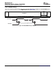
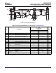
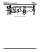
7.10.4 HOLD/ HOLDA Timing
HOLD
HOLDA
EMIF Bus
(A)
DSP Owns Bus
External Requestor
Owns Bus
DSP Owns Bus
DSP DSP
1
3
2 5
4
AECLKOUT
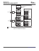
SM320C6455-EP
FIXED-POINT DIGITAL SIGNAL PROCESSOR
SPRS462B – SEPTEMBER 2007 – REVISED JANUARY 2008
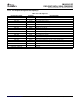
Table 7-48. Timing Requirements for the HOLD/ HOLDA Cycles for EMIFA Module
(1)
(see Figure 7-39 )
-720
-850
A-1000/-1000
NO. UNIT
-1200
MIN MAX
3 t
h(HOLDAL-HOLDL)
Hold time, HOLD low after HOLDA low E ns
(1) E = the EMIF input clock (ECLKIN) period in ns for EMIFA.
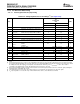
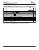
Table 7-49. Switching Characteristics Over Recommended Operating Conditions for the HOLD/ HOLDA
Cycles for EMIFA Module
(1) (2)
(see Figure 7-39 )
-720
-850
A-1000/-1000
NO. PARAMETER UNIT
-1200
MIN MAX
1 t
d(HOLDL-EMHZ)
Delay time, HOLD low to EMIFA Bus high impedance 2E
(3)
ns
2 t
d(EMHZ-HOLDAL)
Delay time, EMIF Bus high impedance to HOLDA low 0 2E ns
4 t
d(HOLDH-EMLZ)
Delay time, HOLD high to EMIF Bus low impedance 2E 7E ns
5 t
d(EMLZ-HOLDAH)
Delay time, EMIFA Bus low impedance to HOLDA high 0 2E ns
(1) E = the EMIF input clock (ECLKIN) period in ns for EMIFA.
(2) EMIFA Bus consists of: ACE[5:2], ABE[7:0], AED[63:0], AEA[19:0], ABA[1:0], AR/ W, ASADS/ ASRE, AAOE/ ASOE, and AAWE/ ASWE.
(3) All pending EMIF transactions are allowed to complete before HOLDA is asserted. If no bus transactions are occurring, then the
minimum delay time can be achieved.
A. EMIFA Bus consists of: ACE[5:2], ABE[7:0], AED[63:0], AEA[19:0], ABA[1:0], AR/ W, ASADS/ ASRE, AAOE/ ASOE,
and AAWE/ ASWE.
Figure 7-39. HOLD/ HOLDA Timing for EMIFA
Submit Documentation Feedback C64x+ Peripheral Information and Electrical Specifications 171