
Car Stereo System - Car Radio Digital Signal Processor User Manual


www.ti.com
7.4 Enhanced Direct Memory Access (EDMA3) Controller
SM320C6455-EP
FIXED-POINT DIGITAL SIGNAL PROCESSOR
SPRS462B – SEPTEMBER 2007 – REVISED JANUARY 2008
The primary purpose of the EDMA3 is to service user-programmed data transfers between two
memory-mapped slave endpoints on the device. The EDMA3 services software-driven paging transfers
(e.g., data movement between external memory and internal memory), performs sorting or subframe
extraction of various data structures, services event driven peripherals such as a McBSP or the UTOPIA
port, and offloads data transfers from the device CPU.
The EDMA3 includes the following features:
• Fully orthogonal transfer description
– Three transfer dimensions: array (multiple bytes), frame (multiple arrays), and block (multiple
frames)
– Single event can trigger transfer of array, frame, or entire block
– Independent indexes on source and destination
• Flexible transfer definition:
– Increment or FIFO transfer addressing modes
– Linking mechanism allows for ping-pong buffering, circular buffering, and repetitive/continuous
transfers, all with no CPU intervention
– Chaining allows multiple transfers to execute with one event
• 256 PaRAM entries
– Used to define transfer context for channels
– Each PaRAM entry can be used as a DMA entry, QDMA entry, or link entry
• 64 DMA channels
– Manually triggered (CPU writes to channel controller register), external event triggered, and chain
triggered (completion of one transfer triggers another)
• Four Quick DMA (QDMA) channels
– Used for software-driven transfers
– Triggered upon writing to a single PaRAM set entry
• Four transfer controllers/event queues with programmable system-level priority
• Interrupt generation for transfer completion and error conditions
• Memory protection support
– Active memory protection for accesses to PaRAM and registers
• Debug visibility
– Queue watermarking/threshold allows detection of maximum usage of event queues
– Error and status recording to facilitate debug
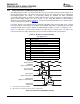
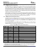
Each of the transfer controllers has a direct connection to the switched central resource (SCR).
NOTE
Although the transfer controllers are directly connected to the SCR, they can access only
certain device resources. For example, only transfer controller 1 (TC1) can access the
McBSPs. Table 4-1 lists the device resources that can be accessed by each of the
transfer controllers.
Submit Documentation Feedback C64x+ Peripheral Information and Electrical Specifications 109