
Reference Guide


4
S6500 Long Range Reader Module - Reference Guide May ’01
Document Overview
Page
Chapter 1: Introduction. . . . . . . . . . . . . . . . . . . . . . . . . . . . . . . . . . . . . . . . . . . . . . . . . . . . . . . . . . . . 6
1.1 General .................................................................................................................... 7
1.2 System Description .................................................................................................. 7
1.3 Product Description .................................................................................................. 7
1.4 Communications Protocols....................................................................................... 8
1.5 Delivery .................................................................................................................... 8
Chapter 2: Reader Hardware . . . . . . . . . . . . . . . . . . . . . . . . . . . . . . . . . . . . . . . . . . . . . . . . . . . . . . . 9
2.1 General .................................................................................................................. 10
2.2 Mechanical Information .......................................................................................... 10
2.3 Connectors............................................................................................................. 11
2.4 Reader Module LEDs............................................................................................. 15
2.5 Switches................................................................................................................. 16
Chapter 3: Installation. . . . . . . . . . . . . . . . . . . . . . . . . . . . . . . . . . . . . . . . . . . . . . . . . . . . . . . . . . . . 17
3.1 Introduction ............................................................................................................ 18
3.2 General .................................................................................................................. 18
3.3 Mechanical Mounting ............................................................................................. 18
3.4 Connectors............................................................................................................. 20
3.5 Interface Configuration Jumper Settings ................................................................ 24
3.6 Setting Bus Addresses ........................................................................................... 25
Chapter 4: Technical Data . . . . . . . . . . . . . . . . . . . . . . . . . . . . . . . . . . . . . . . . . . . . . . . . . . . . . . . . 26
4.1 Specification Summary........................................................................................... 27
4.2 Mechanical Information .......................................................................................... 28
Chapter 5: Regulatory, Safety and Warranty Notices . . . . . . . . . . . . . . . . . . . . . . . . . . . . . . . . . . 29
5.1 Regulatory Notes ................................................................................................... 30
5.2 Safety Precautions ................................................................................................. 31
5.3 Warranty and Liability............................................................................................. 31
List of Figures
Page
Figure 1: S6500 Long Range Reader Module (RI-STU-650A)........................................... 7
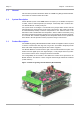
Figure 2: Top View Upper and (part of) Lower pcb .......................................................... 10
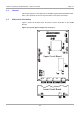
Figure 3: Reader Mounting Holes..................................................................................... 19
Figure 4: Supply Voltage Connector X3 ........................................................................... 20
Figure 5: Antenna Line on a Ring Core............................................................................ 21
Figure 6: Optocoupler Input - Internal and External Wiring .............................................. 21
Figure 7: Optocoupler Outputs ......................................................................................... 22
Figure 8: Relay Connector................................................................................................ 23
Figure 9: RS485 Interface ................................................................................................ 23
Figure 10: RS232 Interface .............................................................................................. 23
Figure 11: RS232 Interface Line on a Ring Core ............................................................. 24
Figure 12: Jumper Settings for RS232 ............................................................................. 24
Figure 13: Jumper Settings for RS485 ............................................................................. 24
Figure 14: Jumper Settings for RS485 Line Termination ................................................. 25