
Reference Guide


24
S6500 Long Range Reader Module - Reference Guide May ’01
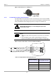
Figure 11: RS232 Interface Line on a Ring Core
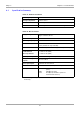
3.5 Interface Configuration Jumper Settings
There are five jumpers used on the reader. They are Jumpers J400 - J401 which are
used to configure the asynchronous interface for RS232 or RS485 described in Table
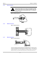
17, and Jumpers J403, J405 and J407 are used to insert the termination resistors
which may be required for the RS485 interface, described in Table 18 and shown in
Figure 14.
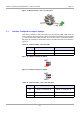
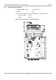
Figure 12: Jumper Settings for RS232
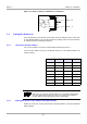
Figure 13: Jumper Settings for RS485
Table 17: Jumper Setting - J400 and J401
Jumper RS232 RS485
400 1 - 2 connected 2 - 3 connected
401 1 - 2 connected 2 - 3 connected
Table 18: Jumper Setting - J403, J405 and J407
Jumper In Out
403
Termination resistor between
RS485 - A and RS485 - B
No termination resistor between
RS485 - A and RS485 - B
405 Pull-Up on RS485 - B No Pull-Up on RS485 - B
407 Pull-Down on RS485 - A No Pull-Down on RS485 - A
J401
J400
1
1
J401
J400
1
1