
Reference Guide


23
May ’01 Chapter 3. Installation
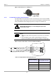
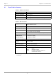
3.4.5 Relay Connector
Figure 8: Relay Connector
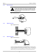
3.4.6 RS485 Connection
Figure 9: RS485 Interface
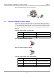
3.4.7 RS232 Connection
Figure 10: RS232 Interface
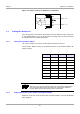
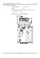
In order to conform to national requirements for radio devices, the interface connec-
tor line must incorporate one of the ring cores mention in section 1.5. The cable must
be wound around the core at least eight times as shown in Figure 11. The distance
between the ring core and the reader connection must not be more than 10 cm.
CAUTIONS:
The two relay change-over contacts are designed to switch
resistive loads only. If you are using an inductive load, the
relay contacts must be protected by means of an external
protection circuit.
X11
1
2
3
common
normally open
normally closed
1
2
3
4
5
6
X9
Tx+/Rx+
Tx-/Rx -
GND
n.c.
n.c.
n.c.
1
2
3
X10
GND
RXD
TXD
5
3
2
9-pin sub-D female