
Reference Guide


21
May ’01 Chapter 3. Installation
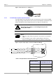
Figure 5: Antenna Line on a Ring Core
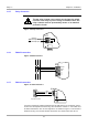
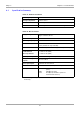
3.4.3 Isolated Optocouplers Input Connector
The input LED's on the optocouplers have an internal input series resistor of 500 Ω.
For supply voltages above 10V the input current must be limited to a maximum of 20
mA by an additional external dropping resistor (see Figure 6 and Table 16).
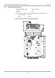
Figure 6: Optocoupler Input - Internal and External Wiring
CAUTION:
Reversing the polarity or overloading the inputs will
destroy the reader.
Notes:
1. If the connecting cable is longer than 3 m you must use a shielded
cable.
2. You must NOT use the reader’s supply voltage to drive these
inputs as the added noise may reduce the effective reading range.
Table 16: Required External Dropping Resistor
External voltage V
ext
Required External
Dropping Resistor R
ext
5 V ... 10 V ---
11 V ... 15 V 270
Ω
16 V ... 20 V 560
Ω
21 V ... 24 V 820
Ω
1
2
3
4
R
int
R
int
IN1 +
IN1 -
IN2 +
IN2 -
R
ext
U
ext
U
ext
R
ext
X7