
Reference Guide


20
S6500 Long Range Reader Module - Reference Guide May ’01
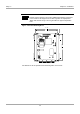
3.4 Connectors
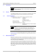
3.4.1 Power Supply Connector
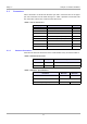
The supply voltage is connected to connector X3 on the lower circuit board.
Figure 4: Supply Voltage Connector X3
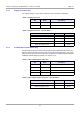
3.4.2 Antenna Connectors (X1 & X2)
The transmit/receive antenna must be connected to the reader via the antenna SMA
socket (X2). The maximum tightening torque for the SMA socket is 0.45 Nm.
If you are using a receive only antenna (together with the read write antenna) it must
be connected to the reader via the antenna SMA socket (X1). The maximum tighten-
ing torque for the SMA socket is 0.45 Nm.
CAUTIONS:
1. Reversing the power supply wires may destroy the
device.
2. If you are using a switched power supply you must
ensure that the switching frequency is below 300 kHz.
Notes:
1. In order to conform to national requirements for radio devices, the
power supply line must incorporate one of the ∅ 28 mm x 20 mm
ring cores mentioned in section 1.5. The cable must be wound
around the core at least eight times (as shown in Figure 11). The
distance between the ring core and the reader connection must
not be more than 10 cm.
2. In order to avoid interference, the length of the cable between the
power supply and the reader must not exceed 3 m.
Notes:
1. In order to conform to national requirements for radio devices,
each antenna line must incorporate one of the ∅ 28 mm x 20 mm
ring cores mentioned in section 1.5. The cable must be wound
around the core at least four times (as shown in Figure 5). The
distance between the ring core and the reader connection must
not be more than 10 cm.
2. When connecting an antenna, ensure that it does not exceed the
permissible limits as prescribed by the national regulations for
radio frequency devices.
X3
X1
1
2
+24 V DC
GND
!