
Reference Guide


18
S6500 Long Range Reader Module - Reference Guide May ’01
3.1 Introduction
3.2 General
The S6500 Reader Module has been designed with easy installation in mind. The fol-
lowing information provides you with any details that you will need to know.
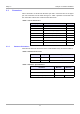
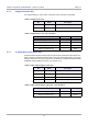
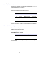
3.2.1 Default Configuration
The S6500 Reader is delivered with the default configuration as follows:
- Communication Interface: 38400 Baud,
8 data bits,
1 stop bit, even parity
- Antenna Connection: Only TX/RX Antenna active
- Anticollision procedure: active
- Supported Transponder Types: Tag-it HF,
Tag-it HF-I (and other ISO 15693 compliant
transponders)
However, if your system requires that you use the reader with a different configura-
tion, you can use the S6 Reader Utility program which is available at our internet site
http://www.ti-rfid.com (S/W Tools & Download) to re-configure the reader to your sys-
tem’s requirements.
3.3 Mechanical Mounting
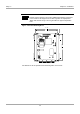
Mounting is accomplished using the 4.5 mm diameter holes located in each corner
of the base plate (see Figure 3). If the antenna is properly tuned and there is sufficient
air convection along the mounting plate, the reader can be operated without an ad-
ditional heat sink at up to 4 W of RF power.
If you are going to operate the reader module above 4 W (to fully exploit the reader’s
performance) it must be mounted on an additional heat sink. The heat sink should
have a thermal resistance R
ThK
of maximum 0.8 K/W. When attaching the Reader
Module to the heat sink you should strive for as little heat transfer resistance between
the base plate and the heat sink as possible. We recommend that you use a heat
sink compound.
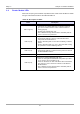
Note:
Always ensure that the reader is switched off when making or break-
ing connections to it.
Note:
If you are only using one transponder Type in the application, the
reaction time of the reader for transponder read/write operations can
be optimized as long as only one transponder driver (not both of
them) is activated.