
Reference Guide


15
May ’01 Chapter 2. Reader Hardware
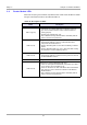
2.4 Reader Module LEDs
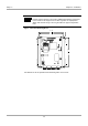
There are five (one green and four red) LEDs on the reader. Their location is shown
in Figure 2 and their function is described in Table 14.
Table 14: Description of LEDs
Name Description
LED V1 (green)
“RUN-LED”
- If all checks are OK this LED comes on (flashes) when V5
goes out. It indicates that the reader’s internal software is
running properly.
- Flashing rate approximately 1 Hz.
- After a firmware change this LED flashes alternately with V5
until a second reset is performed.
LED V2 (red)
Diagnostic 1: RF communication / EEPROM status
- Short flashing indicates error-free communication with a
transponder on the RF interface.
- Flashes alternating with V1 after a Reset following a software
update.
- Flashes alternating with V1 in case a data error while reading
the parameters occurred following a Reset.
LED V3 (red)
Diagnostic 2: Host communication
- Short flashing indicates a protocol is being sent to the host on
the RS232/RS485 interface.
LED V4 (red) Diagnostic 3: Reserved
LED V5 (red)
Diagnostic 4: Reader initialization / RF error
- Comes on during Reader initialization after power-up or after a
reset, and goes out if everything is OK.
- Comes on to indicate an error in the RF section of the Reader.
The error type can be read out via software on the RS232/
RS485 interface.
- After a firmware change this LED flashes alternately with V1
until a second reset is performed.