
Reference Guide


11
May ’01 Chapter 2. Reader Hardware
2.3 Connectors
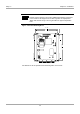
Three connectors are located on the lower pcb and 5 connectors are on the upper
pcb. The connectors are all shown on Figure 2. Table 1 provides an overview of all
the connectors and lists the section that describes them.
2.3.1 Antenna Connectors
There are two antenna connectors on the reader module. They are listed in Table 2.
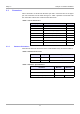
Table 1: List of Connectors
Identifying Letter Function Section
X1 Rx Only Antenna Connection 2.3.1
X2 Tx/Rx Antenna Connection 2.3.1
X3 Voltage Supply 2.3.2
X6 Isolated Optocoupler Outputs 2.3.4
X7 Isolated Optocoupler Inputs 2.3.3
X9 RS485 Interface 2.3.6
X10 RS232 Interface 2.3.7
X11 Relay Outputs 2.3.5
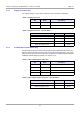
Table 2: Antenna Connectors
Pin Signal Description
X1 ANT Receive Only Antenna
X2 ANT Transmit/Receive Antenna
Table 3: Antenna - Specifications
Parameter Minimum Maximum
Antenna Q-factor 10 30
Antenna Impedance
50 Ω ± (3 Ω ∠
3º
)
Tightening Torque - 0.45 Nm