
Reference Guide


10
S6500 Long Range Reader Module - Reference Guide May ’01
2.1 General
This chapter provides a description of the S6500 Long Range Reader Module hard-
ware. It also provides the electrical specifications of the inputs and outputs.
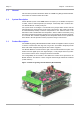
2.2 Mechanical Information
Figure 2 shows the location of the connectors, jumpers and LEDs on the S6500
Reader.
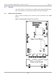
Figure 2: Top View Upper and (part of) Lower pcb
X6 X7 X9 X10
V1
V2
V3
V4
V5
X11
X13
X14
S2
ON
OFF
1 2 3 4
J2
J3
X15
X16
J6
X21
J50
J51
J8
J350
X19
J5
J4
J402
S1
J1
X20
J401
J400
X18
J405
J403
J407
Upper Circuit Board
Lower Circuit Board
X2 X1
X3