
User's Manual


40
S2510 Reader - Reference Guide April ’00
4.9 Antenna
The S251B Reader can be used together with the TIRIS antennas RI-ANT-G01E, RI-
ANT-G02E, RI-ANT-G04E and RI-ANT-S02C. If you wish to use it with your own de-
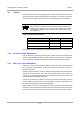
sign antenna that antenna must conform to the specifications given in Table 36.
Table 36: Antenna Specifications
The antenna must be connected to the terminals marked Antenna on the S251B.
4.10 RF Power Output Adjustment
Use the RF Power Output Adj. potentiometer to adjust the internal oscillator pulse
width and subsequently the antenna output voltage to conform to your local regula-
tions. Turning the potentiometer clockwise causes the field strength to increase.
4.11 EMI / Sync. Level Adjustment
EMI / Sync. Level Adj. potentiometer to adjust the receiver signal strength threshold
for the wireless synchronization. Turning the potentiometer clockwise results in a
maximum sensitivity.
If wireless synchronization is used, it is important that the EMI/Sync level Adj. poten-
tiometer is correctly adjusted. This is one of the final adjustments to the reader and
is done on site in the final location once the antenna has been tuned and ALL THE
OTHER READER ARE SWITCHED OFF.
Turning the potentiometer adjusts the receiver signal level threshold and you must
set the reader’s ‘base level noise’ in its final location, so that any signal larger than
the base level triggers the synchronization algorithm.
Send a single ‘X’ (execute command) to the reader to stop any continuous reading,
and then turn the potentiometer clockwise until the yellow LED is fully lit. Slowly ad-
just the potentiometer back until the LED just goes out. Adjustment is then complete.
Note:
The Stick Antenna (RI-ANT-S02C) must only be used together with a
reader supply voltage up to 12 V. If you use this antenna with a higher
reader supply voltage the antenna becomes too warm which effects
the antenna’s Q.
Parameter Minimum Maximum
Antenna Resonance Voltage - 380 Vpeak
Antenna Inductance 26.0
µ
H 27.9
µ
H
Antenna Q-factor 40 350