
User's Manual


39
April ’00 Chapter 4. Installation
4.7 LED Outputs
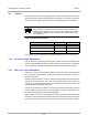
The signals used for the indicator LEDs (Read O.K. and Transmitting) are available
at Indicator Outputs connector (H), they can be used to drive external LEDs or buzz-
ers, they must be connected as shown in Figure 14. Ensure that the values given Ta-
ble 18 are not exceeded.
Figure 14: Connecting the LED Outputs
4.8 Reset
The S251B Reader provides a connection for an external reset on pin 12 of the Gen-
eral Purpose Input / Output connector (B). This pin can be used reset the S251B
Reader externally. You can apply an external reset to the reader by connecting a
push-button to the connectors as shown in Figure 15.
Figure 15: RESET Push-button Wiring
GENERAL I/O PORT
RESET-
GND
12
15