
User's Manual


35
April ’00 Chapter 4. Installation
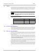
4.5.4 Master/Slave (without acknowledgement) & Triggered Synch.
Figure 11 shows the way that the Readers have to be connected for master/slave
synchronization without acknowledgment; and triggered synchronization. Make sure
that you set the software configuration to Master or Slave (according to Table 32 and
Table 33) acknowledgement) when you are configuring the reader.
Table 32 and Table 33 show the settings of the Line termination DIP switches.
Figure 11
: Master/Slave Sync. Interface Connection (without Ack.)
Table 32: Master/Slave Synchronization Without Acknowledgement
Line Termination
Dip Switch
Unit 1:
(Master)
Unit 2...Unit n-1:
(Slaves)
UNIT n: (Slave)
SW1 ON OFF ON
SW2 ON OFF ON
SW3 OFF OFF ON (see Note)
Note:
If the distance between Unit 1 and Unit n is less than approximately
400 m, DIP switch SW3 can be left OFF.
Table 33: Triggered Synchronization
Line
Termination
Dip Switch
UNIT 1:
Trigger Unit
UNIT 2...UNIT n-1:
(Master)
UNIT n: (Master)
SW1 Termination not required OFF ON
SW2 Termination not required OFF ON
SW3 Termination not required OFF ON (see Note)