
User's Manual


33
April ’00 Chapter 4. Installation
Figure 8: Switch Settings for RS422
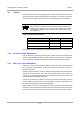
4.4.4 RS485
Connect the WECO (marked RS422 / 485) connector as shown in Table 30. Set the
switches as shown in Figure 9. If you are only using one reader the line terminal
switch 3 must be switched to ON, if you are using more than one reader only the last
reader in the line must be switched to ON (all other readers to OFF).
Figure 9: Switch Settings for RS485
Table 30: RS422/RS485 Connector
Pin Signal Description
Direction
RS422
Direction
RS485
1Rx+/Tx+
RS422/RS485 non-
inverted data
Input Input/Output
2 Rx-/Tx-
RS422/RS485
inverted data
Input Input/Output
3 GND Signal Ground - -
4Tx+
RS422 non-inverted
data
Output/High
Impedance
-
5 Tx- RS422 inverted data
Output/High
Impedance
-
6 GND Signal Ground - -
ON
1
ON
1