
User's Manual


31
April ’00 Chapter 4. Installation
4.4 Communication
Follow the instructions given in the section that describes the communications set-
up that you have decided to use in your system: Section 4.4.2 for RS232, Section
4.4.3 for RS422 and Section 4.4.4 for RS485.
4.4.1 Configuration
CTL Setup switch 8 determines the mode of operation of the control module when
power is applied to the control module. When CTL Setup switch 8 is in the OFF po-
sition, standard TIRIS default parameters are used, these are:
- ASCII protocol
- 9600 baud, eight databits, no parity, one stop bit, X
on
/X
off
enabled
- Normal Mode
- Wireless synchronization
- I/O 0 to 3 defined as input
- I/O 4 to 7 defined as output and logic high
- Hardware interface RS232C
If CTL Setup switch 8 is in the ON position, customer specific parameters are used
to operate the Control Module. These application specific parameters are stored in
the serial EEPROM on the Control Module.
You can use the Software Utility Program which is available on the internet at our
site:
http://www.tiris.com
to configure your reader.
In order to configure the reader for customer specific parameters you must connect
the reader via the RS232 port (connector F1 or F2) to your host and get connection
using the TIRIS standard parameters (with CTL Setup switch 8 is in the OFF posi-
tion). Change the default parameters to the customer specific parameters and save
them. Set CTL Setup switch 8 to the ON position and reset the reader. The reader
will then work with the customer specific parameters.
4.4.2 RS232
Either connect a 9-pin SUB-D female plug to the SUB-D connector, or connect up the
6-pin WECO connector marked “RS232” on the reader’s front panel, the pin signals
are given in Table 28 or Table 29.
Note:
The setting of CTL Setup switch 8 is only checked after power on.
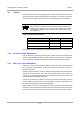
Table 28: RS232 9-pin Connector
Pin Signal Description Direction
1 - Not connected -
2 TxD Transmit Data Output
3 RxD Receive Data Input
4 DTR Data Terminal Ready Input