
User's Manual


17
April ’00 Chapter 2. Hardware
2.2.1.6 F1 & F2 - RS232 Communication Interface
Depending on the DIP-Switch configuration, the Reader will either communicate via
the RS232, RS422 or RS485 interface.
There are two interface connectors either of which can be used for an RS232C con-
nection. They are: a standard RS232 Interface 9-pin SUB-D male connector (F1 on
Figure 3) and a 6-pin WECO connector (F2 on Figure 3). Both of these connectors
allow communication between the reader and a controlling device. The pin assign-
ment for the SUB-D connector is given in Table 13 and the pin assignment for the
WECO connector is given in Table 14.
Both, the ASCII and TIRIS Bus protocol can be used with the RS232 interface.
All interface parameters are according to the RS232 specification and are not given
in detail in this manual. The DTR and DSR lines are currently not used for any pur-
pose.
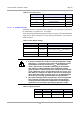
Table 13: RS232 SUB-D Connector
Pin Signal Description Direction
1 - Not connected -
2 TxD Transmit Data Output
3 RxD Receive Data Input
4 DTR Data Terminal Ready Input
5 GND Signal Ground -
6 DSR Data Set Ready Output
7 - Not connected -
8 - Not connected -
9 - Not connected -
Table 14: RS232 WECO Connector
Pin Signal Description Direction
1 RxD Receive Data Input
2 DTR Data Terminal Ready Input
3 GND Signal Ground -
4 TxD Transmit Data Output
5 DSR Data Set Ready Output
6 GND Signal Ground -