
User's Manual


14
S2510 Reader - Reference Guide April ’00
2.2.1.3 C - Synchronization Interface
The synchronization interface is used to establish hard wired synchronization with
other readers through a single or double pair of wires. Its pin assignment is given in
Table 7 and its specifications are given in Table 8.
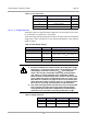
Table 6: General Purpose Inputs/Outputs - Specifications
Parameter Minimum Maximum
GP IO Output Voltage @ 6 mA
Low level
High level
-
3.15 V
0.9 V
5.25 V
General Purpose IO Output Current
Low level
High level
-
-
25 mA
16 mA
GP IO 1 to 4 total Output Current 10 mA
GP IO 5 to 8 total Output Current 10 mA
Regulated 5 V Output Current 100 mA
Table 7: Synchronization Interface
Pin Signal Description Direction
1 Sync Rx+ RS422/RS485 non-inverted synchronization data Input
2 Sync Rx- RS422/RS485 inverted synchronization data Input
3 GND Signal ground -
4 Sync Tx+ RS422/RS485 non-inverted synchronization data Output
5 Sync Tx- RS422/RS485 inverted synchronization data Output
6 GND Signal ground -
Table 8: Synchronization Interface - Specifications
Parameter Specification
Mode of Operation Differential
Number of Drivers On Line 32
Number of Receivers On Line 32
Maximum Cable Length 1200 m
Maximum Data Rate 10 Mbits/s
Maximum Common Mode Voltage +12 V / -7 V
Driver Voltage
High > +1.5 V
Low < -1.5 V
Driver Load 60 mA
Driver Output Short Circuit Limit
150mA to GND
250mA to VCC