
User's Manual


13
April ’00 Chapter 2. Hardware
2.2.1.2 B - General Purpose Inputs/Outputs
The Reader has eight general purpose TTL-Level Inputs/Outputs. By means of the
configuration set-up, they can be set in groups of four to be Input or Output. Further-
more, there is a reset connection and a 5 V regulated output.
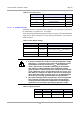
The pin assignment is given in Table 5 and their specifications are given in Table 6.
Table 4: Supply Connector - Specifications
Parameter Minimum Maximum
Logic Supply Voltage VSL 10 V 24 V
Logic Supply current ISL - 2.5 A
Table 5: General Purpose Inputs/Outputs
Pin Signal Description Direction
1 GP IO 7 General Purpose I/O 7 Input/Output
2 GP IO 6 General Purpose I/O 6 Input/Output
3 GP IO 5 General Purpose I/O 5 Input/Output
4 GP IO 4 General Purpose I/O 4 Input/Output
5 GP IO 3 General Purpose I/O 3 Input/Output
6 GP IO 2 General Purpose I/O 2 Input/Output
7 GP IO 1 General Purpose I/O 1 Input/Output
8 GP IO 0 General Purpose I/O 0 Input/Output
9 - not connected -
10 IN1 Input 1 Input
11 IN0 Input 0 Input
12 RESET- Reset Input
13 VCC
Regulated 5 Volt dc Supply
(see note)
Output
14 GND Signal Ground -
15 GND Signal Ground -
CAUTION:
Do not connect any power supply to pin 13 as it would
damage the reader.
The total consumption of the two VCC outputs (General
Purpose Inputs/Outputs pin 13 together with Open Collec-
tor & I/Os - pin 1) must not exceed 500 mA.