
User's Manual


12
S2510 Reader - Reference Guide April ’00
2.2.1.1 A - Supply Connector
The Reader requires a single DC supply voltage (10 to 24 V) through a 2-pin connec-
tor marked with + for positive and – for negative
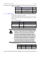
The Power Range Setting wired jumpers (marked J in Figure 3) and the actual power
supply have a direct consequence on the operating temperature of the reader as
shown in Table 2.
1..
F2 RS232 Connector 2.2.1.6
G RS422/RS485 Connector 2.2.1.7
H Indicator Outputs 2.2.1.8
I Antenna Connector 2.2.1.9
Table 2: Power Range Settings
Setting Input Power Operating Temperature Range
Pins 1 + 2 connected 10 - 15 V -20º to +70º C
“ 15 - 24 V
-20º to +70º C
(max. I_VSP = 0.9 A
peak
see caution 1).
Pins 2 + 3 connected 18 - 24 V -20º to +70º C
CAUTION:
1. In order to operate the reader over the full temperature range
with pins 1 + 2 connected (15 to 24 V), the maximum current
consumption must not exceed 0.9 A
peak
. Exceeding this
value could result in unreliable functioning of the dynamic
auto tuning, or sharp limitation of the transmitter output
power because of internal protection. If either of these should
occur, switch the device off and allow it time to recover; and
then when it is switched on again it will revert to normal oper-
ation. Note that if either of these occur it is an indication that
the reader is not being operated within its specifications.
2. The reader itself generates heat, therefore if it is incorporated
into a housing you must ensure (by proper design and/or
cooling) that the temperature immediately surrounding the
reader does not exceed the operating temperature range.
Table 3: Supply Connector
Pin Signal Description Direction
1 + Positive supply input
2 - Ground input
Table 1: List of Connectors
Identifying Letter Function Section