
User's Manual


11
April ’00 Chapter 2. Hardware
2.2.1 Connectors
There are 10 connectors on the S251B, 7 WECO connectors, the antenna connector,
a 9-pin sub-D RS232 connector, a 6-pin connector for the indicator outputs and a 2-
pin connector for the antenna. The function of each pin on each connector (except
the RS232 sub-D connector) is described in the following paragraphs. Their location
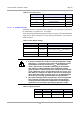
is shown in Figure 3.
Figure 3
:
S251B Connector Locations
In order to gain access to the fuse and connector J you must first remove the upper
two screws holding the front panel on, remove the plastic cover strip and then replace
the two screws. To gain access to the connectors H and I you must first remove the
lower two screws holding the front panel on, remove the plastic cover strip and then
replace the two screws.
The pins are not individually numbered on the connectors themselves (just on Figure
3 for your convenience).
The connectors are all marked on Figure 3 with a letter (from A to I) and are listed in
Table 1 which also shows the section that describes them
Table 1: List of Connectors
Identifying Letter Function Section
A Supply Connector 2.2.1.1
B General Purpose Inputs/Outputs 2.2.1.2
C Synchronization Interface 2.2.1.3
D
Carrier Phase Synchronization
Interface
2.2.1.4
E Open Collector Inputs/Outputs 2.2.1.5
F1 RS232 Connector (9-pin SEB-D) 2.2.1.6
General Purpose Input / Output
Antenna
Power Fuse
Synchronization
+ -
RS422 / 485
RS232
CTL Setup
O.C. - I/O
Read O.K.
TX Active
EMI
Antenna
Tuning
O.K.
L
!
RS422
RS485
DAT
L
"
RF Power Output Adj.
EMI / Sync. Level Adj.
On
Reader S251B
Power Range Setting
12
A
1
15
B
16
C
16
D
16
G
16
F2
16
E F1 H
1
2
I
1 1
1
On
On On
J
123