
Datasheet


Table Of Contents
- FEATURES
- APPLICATIONS
- DESCRIPTION
- ABSOLUTE MAXIMUM RATINGS
- RECOMMENDED OPERATING CONDITIONS
- PACKAGE SPECIFICATIONS
- ELECTRICAL CHARACTERISTICS
- PIN ASSIGNMENT
- TYPICAL CHARACTERISTICS (5-V INPUT) The electrical characteristic data has been developed from actual products tested at 25°C. This data is considered typical for the converter. Applies to , , and . The temperature derating curves represent the conditions at which internal components are at or below the manufacturer's maximum operating temperatures. Derating limits apply to modules soldered directly to a 100-mm × 100-mm, double-sided PCB with 2-oz. copper. Applies to .
- TYPICAL CHARACTERISTICS (12-V INPUT) The electrical characteristic data has been developed from actual products tested at 25°C. This data is considered typical for the converter. Applies to , , and . The temperature derating curves represent the conditions at which internal components are at or below the manufacturer's maximum operating temperatures. Derating limits apply to modules soldered directly to a 100-mm × 100-mm, double-sided PCB with 2-oz. copper. Applies to .
- APPLICATION INFORMATION
- REVISION HISTORY
0
0.25
0.5
0.75
1
0 0.25 0.5 0.75 1 1.25 1.5 1.75 2 2.25
V
O
= 1.5 V
I
O
− Output Current − A
V
O
= 1.2 V
− Power Dissipation − W
P
D
V
O
= 3.3 V
V
O
= 2.5 V
V
O
= 1.8 V
V
O
= 1 V
V
O
= 0.9 V
20
30
40
50
60
70
80
90
0.25 0.75 1.25 1.75 2.25
Airflow
Nat Conv
I
O
− Output Current − A
Temperature Derating − 5 C
40
50
60
70
80
90
100
0 0.25 0.5 0.75 1 1.25 1.5 1.75 2 2.25
Efficiency − %
V
O
= 2.5 V
V
O
= 1.2 V
I
O
− Output Current − A
V
O
= 3.3 V
V
O
= 1.8 V
V
O
= 1.5 V
V
O
= 1 V
V
O
= 0.9 V
V
O
= 2.5 V
V
O
= 1.8 V
I
O
− Output Current − A
− Output Voltage Ripple − mV
V
O PP
0
10
20
30
40
50
0 0.25 0.5 0.75 1 1.25 1.5 1.75 2 2.25
V
O
= 3.3 V
V
O
= 1 V
V
O
= 0.9 V
V
O
= 1.5 V
V
O
= 1.2 V
PTH08080W
www.ti.com
SLTS235D –FEBRUARY 2005–REVISED SEPTEMBER 2013
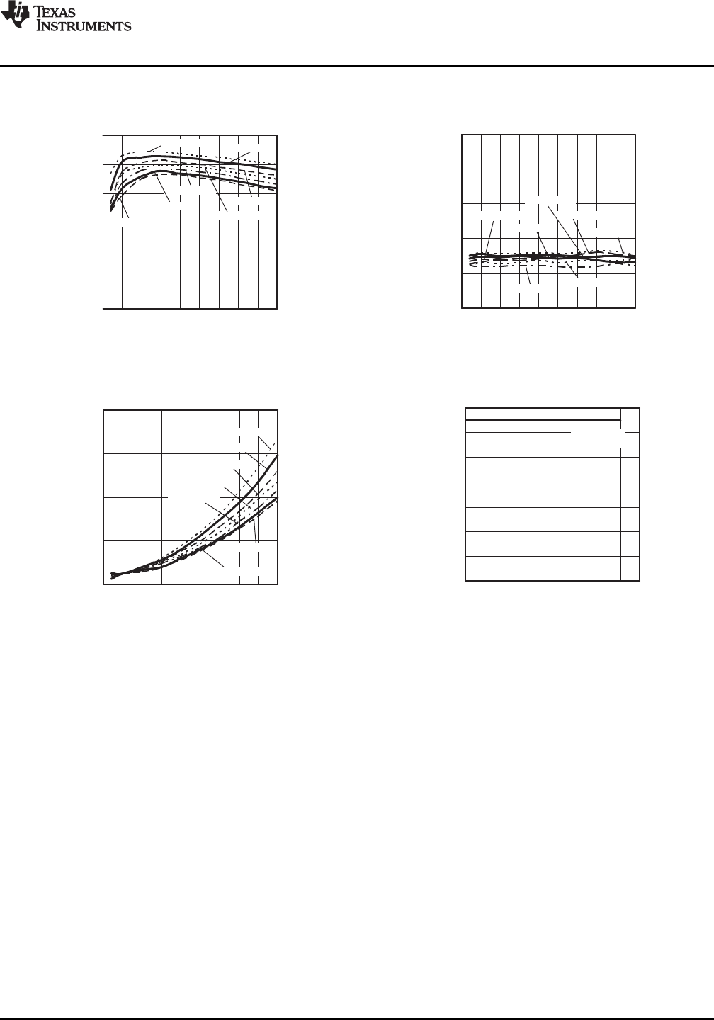
TYPICAL CHARACTERISTICS (5-V INPUT)
(3) (4)
(continued)
EFFICIENCY OUTPUT RIPPLE
vs vs
OUTPUT CURRENT OUTPUT CURRENT
Figure 2. Figure 3.
POWER DISSIPATION TEMPERATURE DERATING
vs vs
OUTPUT CURRENT OUTPUT CURRENT
Figure 4. Figure 5.
Copyright © 2005–2013, Texas Instruments Incorporated Submit Documentation Feedback 5
Product Folder Links :PTH08080W