
Datasheet


Table Of Contents
- FEATURES
- APPLICATIONS
- DESCRIPTION
- ABSOLUTE MAXIMUM RATINGS
- RECOMMENDED OPERATING CONDITIONS
- PACKAGE SPECIFICATIONS
- ELECTRICAL CHARACTERISTICS
- PIN ASSIGNMENT
- TYPICAL CHARACTERISTICS (5-V INPUT) The electrical characteristic data has been developed from actual products tested at 25°C. This data is considered typical for the converter. Applies to , , and . The temperature derating curves represent the conditions at which internal components are at or below the manufacturer's maximum operating temperatures. Derating limits apply to modules soldered directly to a 100-mm × 100-mm, double-sided PCB with 2-oz. copper. Applies to .
- TYPICAL CHARACTERISTICS (12-V INPUT) The electrical characteristic data has been developed from actual products tested at 25°C. This data is considered typical for the converter. Applies to , , and . The temperature derating curves represent the conditions at which internal components are at or below the manufacturer's maximum operating temperatures. Derating limits apply to modules soldered directly to a 100-mm × 100-mm, double-sided PCB with 2-oz. copper. Applies to .
- APPLICATION INFORMATION
- REVISION HISTORY
PTH08080W
www.ti.com
SLTS235D –FEBRUARY 2005–REVISED SEPTEMBER 2013
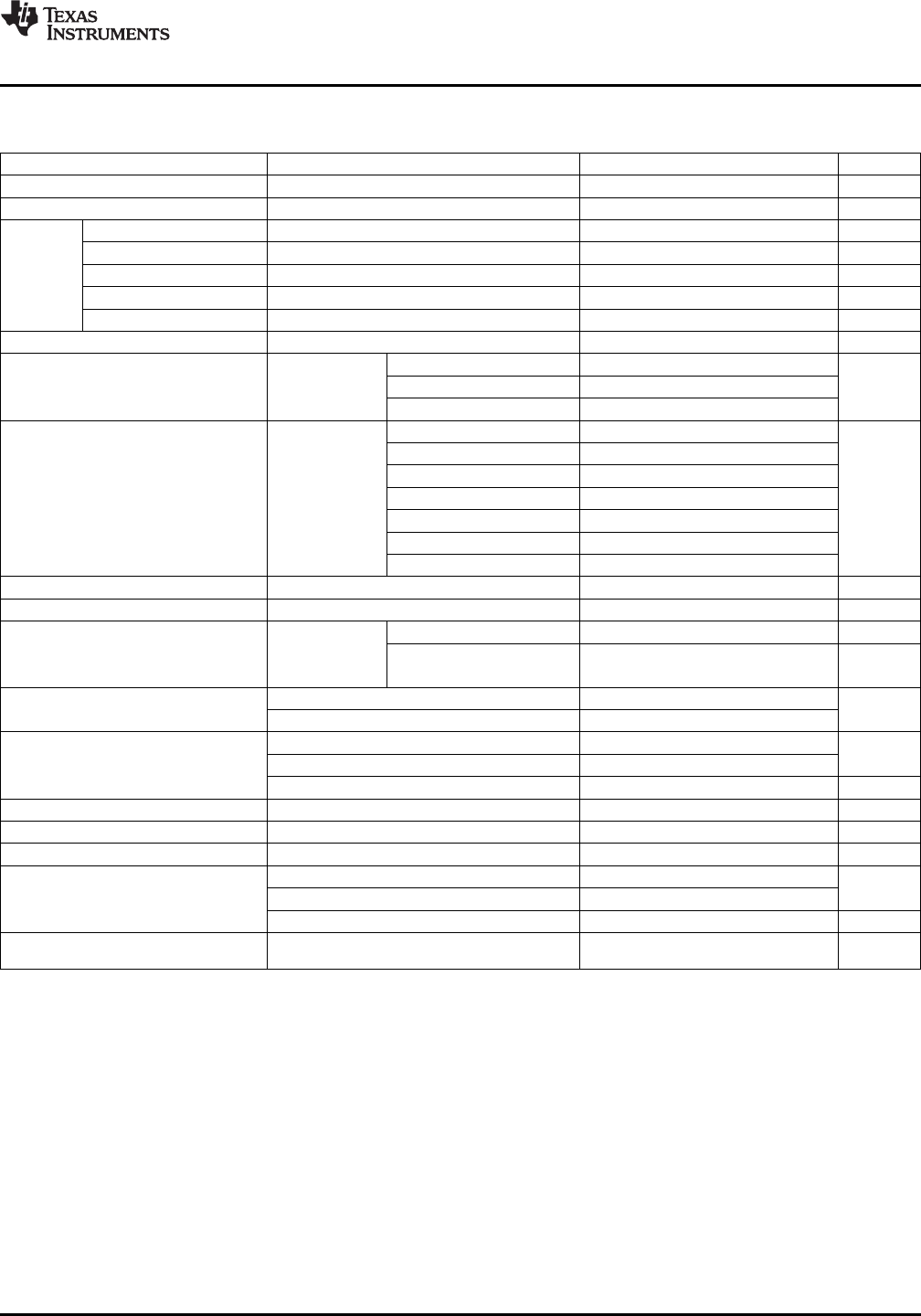
ELECTRICAL CHARACTERISTICS
at 25°C free-air temperature, V
I
= 12 V, V
O
= 3.3 V, I
O
= I
O
max, C
I
= 100 µF, C
O
= 100 µF (unless otherwise noted)
PARAMETER TEST CONDITIONS MIN TYP MAX UNIT
I
O
Output current T
A
= 85°C, natural convection airflow 0 2.25 A
P
O
Output power T
A
= 85°C, natural convection airflow 10 W
Set-point voltage tolerance T
A
= 25°C ±2
(1)
%
Temperature variation -40 ≤ T
A
≤ +85°C ±0.5 %V
o
V
O
Line regulation Over V
I
range ±7 mV
Load regulation Over I
O
range ±0.13 %V
o
Total output voltage variation Includes set-point, line, load, -40 ≤ T
A
≤ +85°C 3
(1)
%V
o
V
ADJ
Output Voltage Adjust Range Over I
O
range 0.9 5.5 V
0.9 V ≤ V
O
≤ 1.8 V 4.5 V
O
x 10
(2)
V
I
Input Voltage Range Over V
O
range 1.8 V < V
O
≤ 3.4 V 4.5 18 V
3.4 V < V
O
≤ 5.5 V V
O
+ 1.1
(2)
18
(2)
R
SET
= 348 Ω, V
O
= 5 V 93.5%
R
SET
= 1.87 kΩ, V
O
= 3.3 V 92%
R
SET
= 3.74 kΩ, V
O
= 2.5 V 91%
T
A
= 25°C,
η Efficiency R
SET
= 6.19 kΩ, V
O
= 2 V 90%
I
O
= 2 A
R
SET
= 8.06 kΩ, V
O
= 1.8 V 89%
R
SET
= 13 kΩ, V
O
= 1.5 V 87.5%
R
SET
= 27.4 kΩ, V
O
= 1.2 V 86.5%
Output voltage ripple 20 MHz bandwith 30 mV
PP
I
O
(trip) Overcurrent threshold Reset, followed by autorecovery 3.5 A
C
O
= 100 µF, 1 Recovery time 50 µs
A/µs load step
Transient response
from 50% to 100%
V
O
over/undershoot 70 mV
I
O
max
V
I
= increasing 4.35 4.5
UVLO Undervoltage lockout V
V
I
= decreasing 3.6 4
Input high voltage (V
IH
) Open
(3)
V
Inhibit control (pin 5) Input low voltage (V
IL
) –0.2 0.5
Input low current (I
IL
) 5 µA
I
I
(stby) Input standby current Pins 5 and 2 connected 1 mA
f
S
Switching frequency Over V
I
and I
O
ranges 300 kHz
External input capacitance Electrolytic type (C
I
) 100
(4)
µF
Ceramic type (C
O
) 220
µF
External output capacitance Nonceramic type (C
O
) 100
(5)
330
(6)
Equivalent series resistance (nonceramic) 10
(7)
mΩ
Per Telcordia SR-332, 50% stress,
MTBF Calculated reliability 48
10
6
Hr
T
A
= 40°C, ground benign
(1) The set-point voltage tolerance is affected by the tolerance and stability of R
SET
. The stated limit is unconditionally met if R
SET
has a
tolerance of 1% with 100 ppm/°C or better temperature stability.
(2) The minimum input voltage is 4.5 V or (V
O
+ 1.1) V, whichever is greater. The maximum input voltage is 18 V or V
O
× 10, whichever is
less.
(3) This control pin has an internal pull-up to 3 V (TYP). Do not place an internal pull-up on this pin. If it is left open-circuit, the module
operates when input power is applied. A small low-leakage (< 100 nA) MOSFET is recommended for control. See the application
information for further guidance.
(4) An external 100-µF electrolytic capacitor is required across the input (V
I
and GND) for proper operation. Locate the capacitor close to
the module.
(5) An external 100-µF electrolytic capacitor is optional across the output (V
O
and GND). Locate the capacitor close to the module.
Additional capacitance close to the load improves the response of the regulator to load transients.
(6) This is the calculated maximum capacitance. The minimum ESR limitation often results in a lower value. See the capacitor application
information for further guidance.
(7) This is the typical ESR for all the electrolytic (nonceramic) capacitance. Use 14 mΩ as the minimum when calculating the total
equivalent series resistance (ESR) using the maximum ESR values specified by the capacitor manufacturer.
Copyright © 2005–2013, Texas Instruments Incorporated Submit Documentation Feedback 3
Product Folder Links :PTH08080W