
Datasheet


Table Of Contents
- FEATURES
- APPLICATIONS
- DESCRIPTION
- ABSOLUTE MAXIMUM RATINGS
- RECOMMENDED OPERATING CONDITIONS
- PACKAGE SPECIFICATIONS
- ELECTRICAL CHARACTERISTICS
- PIN ASSIGNMENT
- TYPICAL CHARACTERISTICS (5-V INPUT) The electrical characteristic data has been developed from actual products tested at 25°C. This data is considered typical for the converter. Applies to , , and . The temperature derating curves represent the conditions at which internal components are at or below the manufacturer's maximum operating temperatures. Derating limits apply to modules soldered directly to a 100-mm × 100-mm, double-sided PCB with 2-oz. copper. Applies to .
- TYPICAL CHARACTERISTICS (12-V INPUT) The electrical characteristic data has been developed from actual products tested at 25°C. This data is considered typical for the converter. Applies to , , and . The temperature derating curves represent the conditions at which internal components are at or below the manufacturer's maximum operating temperatures. Derating limits apply to modules soldered directly to a 100-mm × 100-mm, double-sided PCB with 2-oz. copper. Applies to .
- APPLICATION INFORMATION
- REVISION HISTORY
PTH08080W
SLTS235D –FEBRUARY 2005–REVISED SEPTEMBER 2013
www.ti.com
This integrated circuit can be damaged by ESD. Texas Instruments recommends that all integrated circuits be handled with
appropriate precautions. Failure to observe proper handling and installation procedures can cause damage.
ESD damage can range from subtle performance degradation to complete device failure. Precision integrated circuits may be more
susceptible to damage because very small parametric changes could cause the device not to meet its published specifications.
ORDERING INFORMATION
For the most current package and ordering information, see the Package Option Addendum at the end of this datasheet, or see
the TI website at www.ti.com.
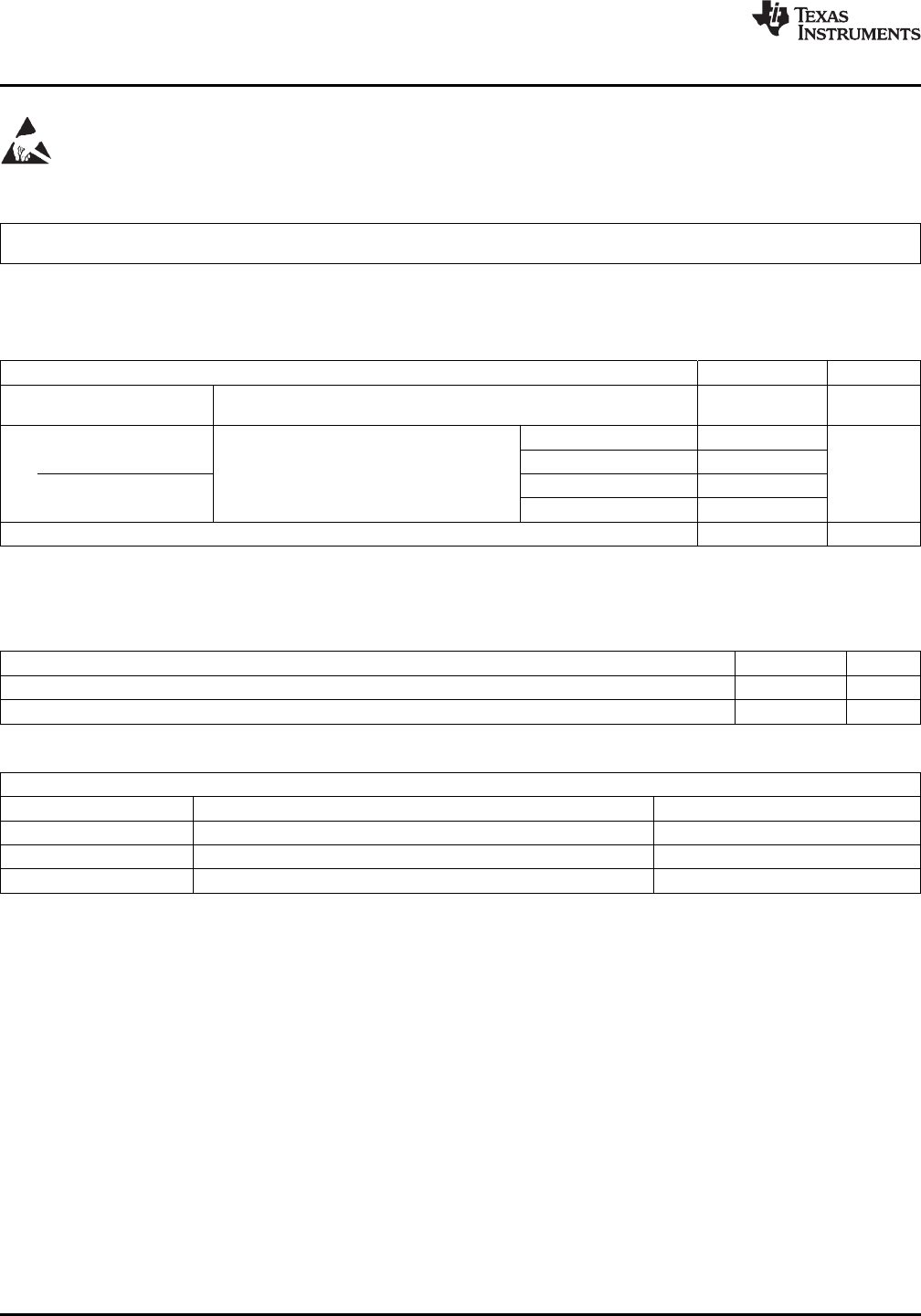
ABSOLUTE MAXIMUM RATINGS
over operating free-air temperature range unless otherwise noted
(1)
PTH08080W UNIT
T
A
Operating free-air Over V
I
range –40 to 85 °C
temperature
Wave Solder Suffix AH 235
temperature
Suffix AD 260
T
S
Surface temperature of module body or pins °C
Solder reflow Suffix AS 235
temperature
Suffix AZ 260
T
stg
Storage temperature –55 to 125 °C
(1) Stresses beyond those listed under absolute maximum ratings may cause permanent damage to the device. These are stress ratings
only, and functional operation of the device at these or any other conditions beyond those indicated under recommended operating
conditions is not implied. Exposure to absolute-maximum-rated conditions for extended periods may affect device reliability.
RECOMMENDED OPERATING CONDITIONS
MIN MAX UNIT
V
I
Input voltage 4.5 18 V
T
A
Operating free-air temperature –40 85 °C
PACKAGE SPECIFICATIONS
PTH08080W (Suffix AH and AS)
Weight 1.5 grams
Flammability Meets UL 94 V-O
Mechanical shock Per Mil-STD-883D, Method 2002.3, 1 ms, 1/2 sine, mounted 500 G
(1)
Mechanical vibration Mil-STD-883D, Method 2007.2, 20-2000 Hz 20 G
(1)
(1) Qualification limit.
2 Submit Documentation Feedback Copyright © 2005–2013, Texas Instruments Incorporated
Product Folder Links :PTH08080W