
Datasheet


Table Of Contents
- FEATURES
- APPLICATIONS
- DESCRIPTION
- ABSOLUTE MAXIMUM RATINGS
- RECOMMENDED OPERATING CONDITIONS
- PACKAGE SPECIFICATIONS
- ELECTRICAL CHARACTERISTICS
- PIN ASSIGNMENT
- TYPICAL CHARACTERISTICS (5-V INPUT) The electrical characteristic data has been developed from actual products tested at 25°C. This data is considered typical for the converter. Applies to , , and . The temperature derating curves represent the conditions at which internal components are at or below the manufacturer's maximum operating temperatures. Derating limits apply to modules soldered directly to a 100-mm × 100-mm, double-sided PCB with 2-oz. copper. Applies to .
- TYPICAL CHARACTERISTICS (12-V INPUT) The electrical characteristic data has been developed from actual products tested at 25°C. This data is considered typical for the converter. Applies to , , and . The temperature derating curves represent the conditions at which internal components are at or below the manufacturer's maximum operating temperatures. Derating limits apply to modules soldered directly to a 100-mm × 100-mm, double-sided PCB with 2-oz. copper. Applies to .
- APPLICATION INFORMATION
- REVISION HISTORY
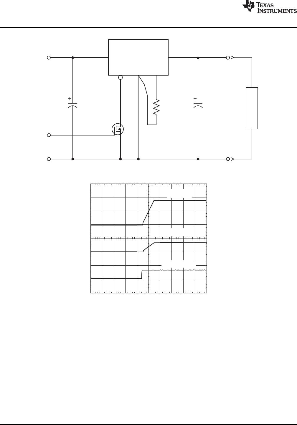
t-Time=5ms/div
Q1V (5V/div)
DS
I (0.5 A/div)
I
V (1V/div)
O
V =12V
I
V =1.8V
O
Inhibit
GND GND
R
SET
8.06kW
0.05W
1%
PTH08080W
2
4
31
5
V Adj
O
GNDInhibit
V
I
V
O
Q1
BSS138
L
O
A
D
C
I
C
O
PTH08080W
SLTS235D –FEBRUARY 2005–REVISED SEPTEMBER 2013
www.ti.com
Figure 12. On/Off Inhibit Control Circuit
Figure 13. Power-Up Response From Inhibit Control
12 Submit Documentation Feedback Copyright © 2005–2013, Texas Instruments Incorporated
Product Folder Links :PTH08080W