
Datasheet


Table Of Contents
- FEATURES
- APPLICATIONS
- DESCRIPTION
- ABSOLUTE MAXIMUM RATINGS
- RECOMMENDED OPERATING CONDITIONS
- PACKAGE SPECIFICATIONS
- ELECTRICAL CHARACTERISTICS
- PIN ASSIGNMENT
- TYPICAL CHARACTERISTICS (5-V INPUT) The electrical characteristic data has been developed from actual products tested at 25°C. This data is considered typical for the converter. Applies to , , and . The temperature derating curves represent the conditions at which internal components are at or below the manufacturer's maximum operating temperatures. Derating limits apply to modules soldered directly to a 100-mm × 100-mm, double-sided PCB with 2-oz. copper. Applies to .
- TYPICAL CHARACTERISTICS (12-V INPUT) The electrical characteristic data has been developed from actual products tested at 25°C. This data is considered typical for the converter. Applies to , , and . The temperature derating curves represent the conditions at which internal components are at or below the manufacturer's maximum operating temperatures. Derating limits apply to modules soldered directly to a 100-mm × 100-mm, double-sided PCB with 2-oz. copper. Applies to .
- APPLICATION INFORMATION
- REVISION HISTORY
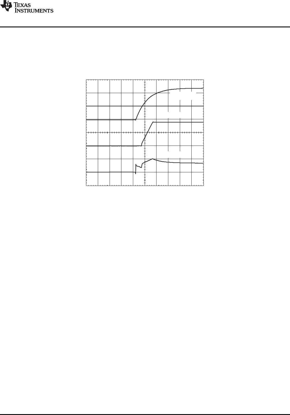
t-Time=5ms/div
I (0.5 A/div)
I
V (1V/div)
O
V (5V/div)
I
PTH08080W
www.ti.com
SLTS235D –FEBRUARY 2005–REVISED SEPTEMBER 2013
Power-Up Characteristics
When configured per the standard application, the PTH08080 power module produces a regulated output voltage
following the application of a valid input source voltage. During power up, internal soft-start circuitry slows the
rate that the output voltage rises, thereby limiting the amount of in-rush current that can be drawn from the input
source. Figure 11 shows the power-up waveforms for a PTH08080W, operating from a 12-V input and with the
output voltage adjusted to 1.8 V. The waveforms were measured with a 2-A resistive load.
Figure 11. Power-Up Waveforms
Current Limit Protection
The PTH08080 modules protect against load faults with an output overcurrent trip. Under a load fault condition,
the output current cannot exceed the current limit value. Attempting to draw current that exceeds the current limit
value causes the output voltage to enter into a hiccup mode of operation, whereby the module continues in a
cycle of successive shutdown and power up until the load fault is removed. On removal of the fault, the output
voltage promptly recovers.
Thermal Shutdown
Thermal shutdown protects the module internal circuitry against excessively high temperatures. A rise in
temperature may be the result of a drop in airflow, a high ambient temperature, or a higher than normal output
current. If the junction temperature of the internal components exceeds 165°C, the module shuts down. This
reduces the output voltage to zero. The module starts up automatically, by initiating a soft-start power up when
the sensed temperature decreases 10°C below the thermal shutdown trip-point.
Output On/Off Inhibit
For applications requiring output voltage on/off control, the PTH08080 power module incorporates an output
on/off Inhibit control (pin 5). The inhibit feature can be used wherever there is a requirement for the output
voltage from the regulator to be turned off.
The power module functions normally when the Inhibit pin is left open-circuit, providing a regulated output
whenever a valid source voltage is connected to V
I
with respect to GND.
Figure 12 shows the typical application of the inhibit function. Note the discrete transistor (Q1). The Inhibit control
has its own internal pull-up to 3 volts. An open-collector or open-drain device is recommended to control this
input. Do not place an external pull-up on this pin.
Turning Q1 on applies a low voltage to the Inhibit control pin and disables the output of the module. If Q1 is then
turned off, the module executes a soft-start power-up sequence. A regulated output voltage is produced within
20 ms. Figure 13 shows the typical rise in the output voltage, following the turn off of Q1. The turn off of Q1
corresponds to the rise in the waveform, Q1 V
DS
. The waveforms were measured with a 2-A resistive load.
Copyright © 2005–2013, Texas Instruments Incorporated Submit Documentation Feedback 11
Product Folder Links :PTH08080W