
Datasheet


Table Of Contents
- FEATURES
- APPLICATIONS
- DESCRIPTION
- ENVIRONMENTAL AND ABSOLUTE MAXIMUM RATINGS
- ELECTRICAL CHARACTERISTICS
- ELECTRICAL CHARACTERISTICS
- TYPICAL CHARACTERISTICSThe electrical characteristic data has been developed from actual products tested at 25C. This data is considered typical for the converter. Applies to , , and .The temperature derating curves represent the conditions at which internal components are at or below the manufacturer's maximum operating temperatures. Derating limits apply to modules soldered directly to a 100 mm x 100 mm double-sided PCB with 2 oz. copper. For surface mount packages (AS and AZ suffix), multiple vias must be utilized. Please refer to the mechanical specification for more information. Applies to .
- TYPICAL CHARACTERISTICSThe electrical characteristic data has been developed from actual products tested at 25C. This data is considered typical for the converter. Applies to , , and .The temperature derating curves represent the conditions at which internal components are at or below the manufacturer's maximum operating temperatures. Derating limits apply to modules soldered directly to a 100 mm x 100 mm double-sided PCB with 2 oz. copper. For surface mount packages (AS and AZ suffix), multiple vias must be utilized. Please refer to the mechanical specification for more information. Applies to .
- APPLICATION INFORMATION
- ADJUSTING THE OUTPUT VOLTAGE
- CAPACITOR RECOMMENDATIONS FOR THE PTH04T240/241W POWER MODULE
- TurboTrans Technology
- TurboTrans Selection
- UNDERVOLTAGE LOCKOUT (UVLO)
- Soft-Start Power Up
- On/Off Inhibit
- Smart Sync
- Overcurrent Protection
- Overtemperature Protection (OTP)
- Differential Output Voltage Remote Sense
- Auto-Track Function
- Tape & Reel and Tray Drawings
2 5
3 4
6
7
10 9
11
Inhibit/
ProgUVLO
GND
TurboTransAutoTrack
8
L
O
A
D
GNDGND
TurboTrans
+Sense
V
O
−Sense
V
O
Adj
V
I
V
I
V
O
+Sense
R
TT
0kW
C
I
220 Fm
(Required)
C
O
1220 F
TypeB
m
R
SET
1%
0.05W
PTH04T240W
−Sense
1
Smart
Sync
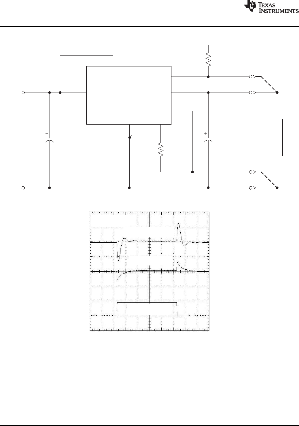
Without TurboTrans
(50 mV/div)
PTH04T240W
C
O
= 1220 µF
2.5 A/µs
50% Load Step
With TurboTrans
(50 mV/div)
T − Time − 200 µs/div
PTH04T240W , PTH04T241W
SLTS276D – OCTOBER 2006 – REVISED JULY 2009 ......................................................................................................................................................
www.ti.com
Figure 16. Typical TurboTrans™ Application
Figure 17. Typical TurboTrans Waveforms
22 Submit Documentation Feedback Copyright © 2006 – 2009, Texas Instruments Incorporated
Product Folder Link(s): PTH04T240W PTH04T241W