
Datasheet


Table Of Contents
www.ti.com
Jumpers, Connectors, Test Points, Switches
1.6 Jumpers, Connectors, Test Points, Switches
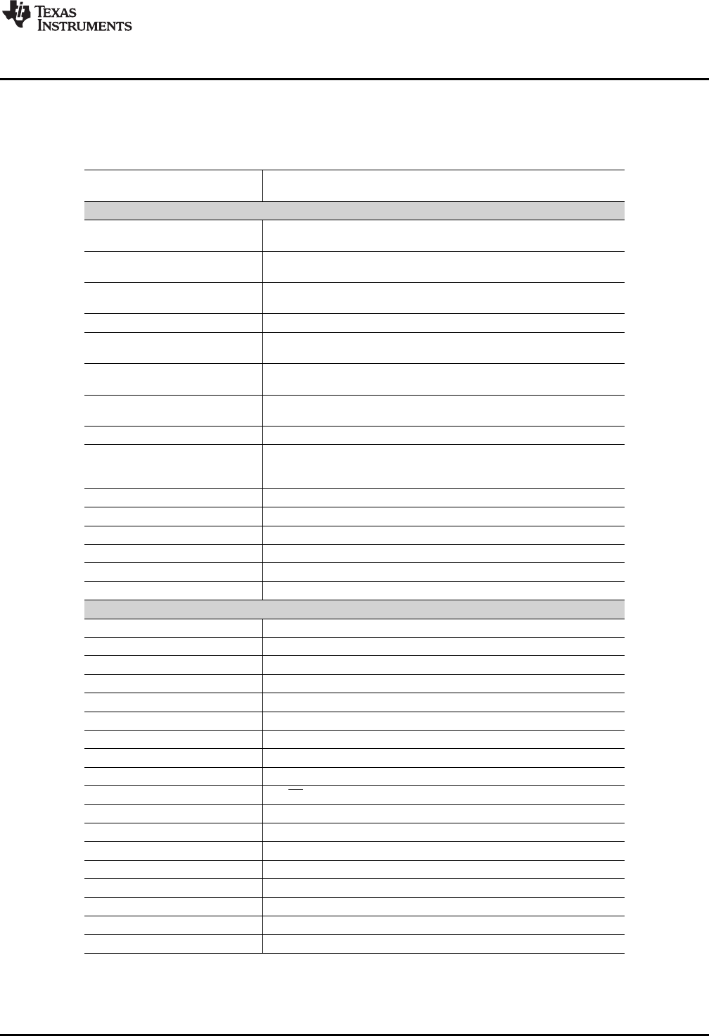
Table 1-1 summarizes the connectors, test points, jumpers, and switches on the PCM9211EVM.
Table 1-1. PCM9211EVM Jumpers, Connectors, Test Points, Switches
Connector/Switch/Jumper/Test
Point Description
Headers
W1 VCCAD wire loop. Cut and insert ampere meter to measure VCCAD
current.
W2 Right channel analog RC filter bypass. Insert shunt to bypass the
filter.
W3 Right channel analog RC filter bypass. Insert shunt to bypass the
filter.
W4 VCC wire loop. Cut and insert ampere meter to measure VCC current.
W5 VDDRX wire loop. Cut and insert ampere meter to measure VDDRX
current.
W6 Control interface MODE select. Insert shunt to select I
2
C™ interface.
Remove shunt to select SPI interface.
W7 DVDD wire loop. Cut and insert ampere meter to measure DVDD
current.
W8 Optical S/PDIF output select. 1-2: Select MPO0, 2-3: Select MPO1.
W9 Digital audio interface option. Insert shunt to connect the
PCM9211digital audio interface output to the TAS1020b digital audio
interface (required to record audio).
W10 Coaxial S/PDIF input select:1-2: Select RXIN0, 2-3: Select RXIN1
W11 11-pin header to access RXIN2:7 and digital audio interface (AxxxIO).
W12
(1)
SPI SS / ADR1: 1-2: ADR1 = 0 (I2C), 2-3: SPI mode select
W13
(1)
Control IF clock: 1-2: I2C mode select, 2-3: SPI mode select
W14
(1)
Control IF data: 1-2: I2C mode select, 2-3: SPI mode select
W15
(1)
Control IF data: 1-2: ADR0 = 0 (I2C), 2-3: SPI mode select
Test Points
TP1 I
2
C SCL
TP2 I
2
C SDA
TP3 TAS1020b MCLK
TP4 TAS1020b I
2
S DIN to codec
TP5 I
2
S BCLK
TP6 TAS1020b I
2
S DOUT from codec
TP7 TAS1020b I
2
S WCLK
TP8 SPI MISO
TP9 SPI MOSI
TP10 SPI SS
TP11 SPI SCLK
TP12 Codec reset
TP13 XTI
TP14 Control interface MODE
TP15 +5-V USB
TP16 +3.3 V
TP17 GND
TP18 GND
(1)
All W12-W15 settings must be the same for proper operation.
9
SBAU174–June 2010 Description
Copyright © 2010, Texas Instruments Incorporated