Datasheet
Manuals
Brands
TEXAS INSTRUMENTS Manuals
Linear ICs
Linear-IC
21
22
23
24
25
26
27
28
29
30
Table Of Contents
FEATURES
APPLICATIONS
DESCRIPTION
ABSOLUTE MAXIMUM RATINGS
RECOMMENDED OPERATING CONDITIONS
ELECTRICAL CHARACTERISTICS
DEVICE INFORMATION
PIN ASSIGNMENTS
FUNCTIONAL BLOCK DIAGRAM
TYPICAL PERFORMANCE CURVES OF INTERNAL FILTER
ADC Digital Decimation Filter Frequency Response
ADC Digital High-Pass Filter Frequency Response
ADC Analog Antialiasing Filter Frequency Response
DAC Digital Interpolation Filter Frequency Response
DAC Analog FIR Filter Frequency Response
DAC Analog Low-Pass Filter Frequency Response
TYPICAL PERFORMANCE CURVES
ADC
DAC
Supply Current
USB INTERFACE
Device Configuration
Interface #0
Interface #1
Interface #2
Endpoints
Internal Regulator
Clock and Reset
DAC
ADC
Microphone Bias
Microphone Amplifier
Input PGA
Sidetone Programmable Attenuator
Output Programmable Attenuator
VCOM1 and VCCM2
Filter Pins
INTERFACE SEQUENCE
Power-On, Attach, and Play Back Sequence
Play Stop and Detach Sequence
Record Sequence
Suspend and Resume Sequence
TYPICAL CIRCUIT CONNECTION
Related Documentation from Texas Instruments
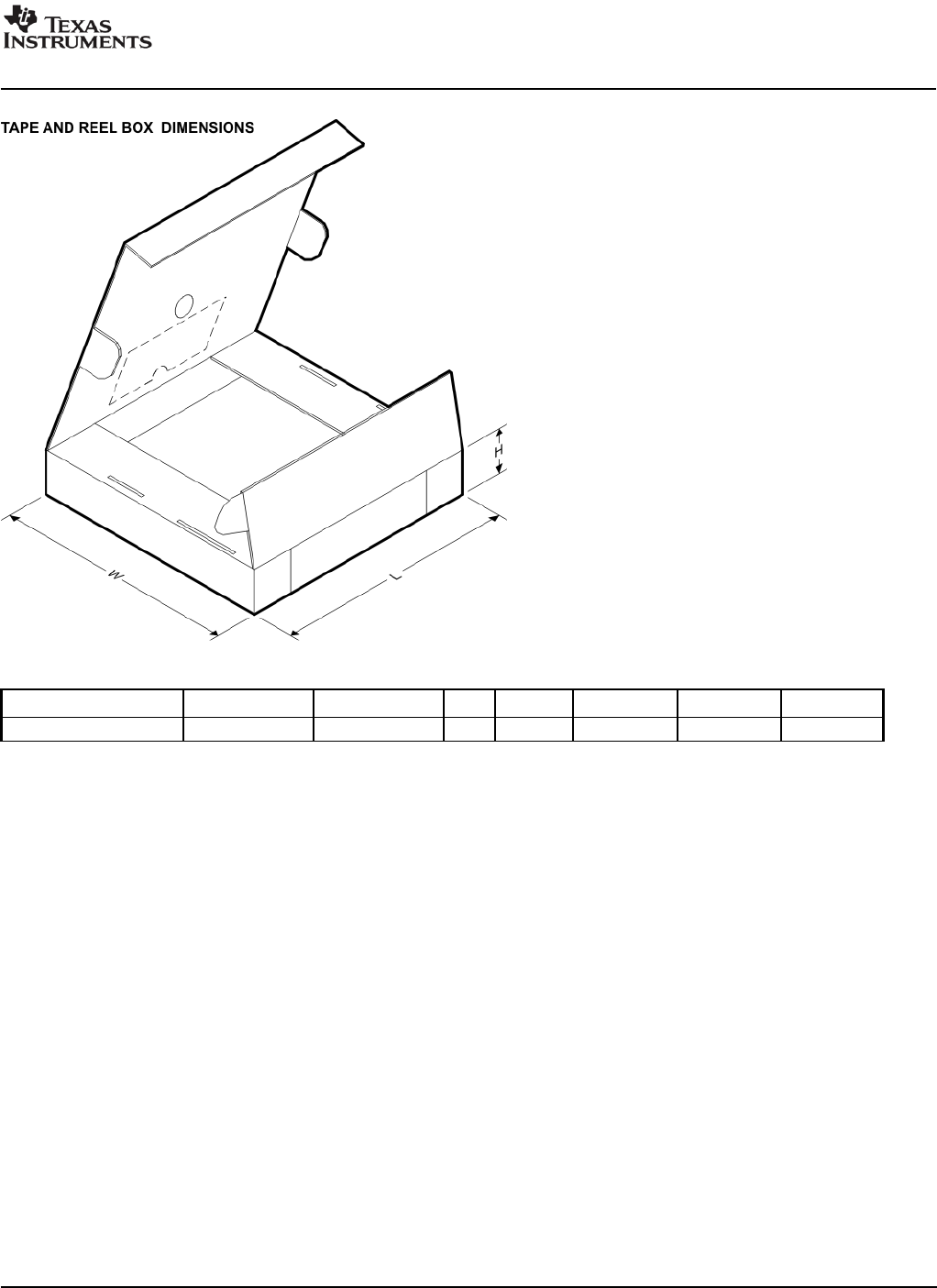
*All dimensions are nominal
Device
Package Type
Package Drawing
Pins
SPQ
Length (mm)
Width (mm)
Height (mm)
PCM2912PJTR
TQFP
PJT
32
1000
346.0
346.0
33.0
PACKAGE MATERIALS INFORMATION
www.ti.com
19-Jul-2008
Pack Materials-Page 2
1
...
...
28
29
30
31
32