
Datasheet


Table Of Contents
- FEATURES
- APPLICATIONS
- DESCRIPTION
- ABSOLUTE MAXIMUM RATINGS
- RECOMMENDED OPERATING CONDITIONS
- ELECTRICAL CHARACTERISTICS
- DEVICE INFORMATION
- TYPICAL PERFORMANCE CURVES OF INTERNAL FILTER
- TYPICAL PERFORMANCE CURVES
www.ti.com
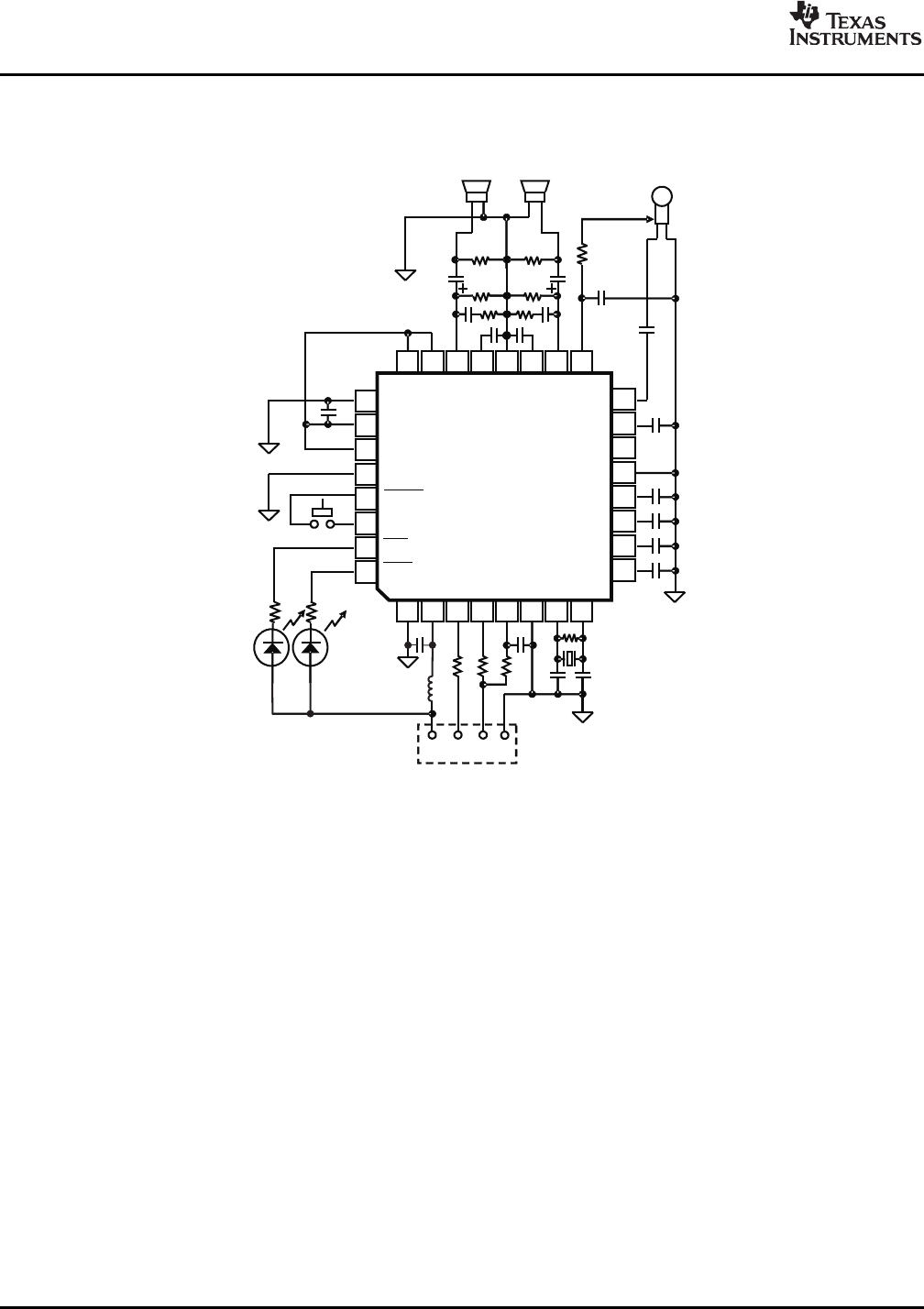
TYPICAL CIRCUIT CONNECTION
R1 R2
654321
87
26
25
32
31
30
29
28
27
9
10
11
12
13
14
15
16
1718
192021222324
POWER MBIAS
BGND
TEST1
TEST0
SSPND
MMUTE
REC
PLAY
PGND
PCM2912
FL
FR
V
COM 1
V
COM 2
AGND
N.C.
V
CCA
V
IN
X1
C2
R4
V
BUS
D – D+ GND
USBConnector
C3
C1
Microphone
Headphone
PLAY
REC.
MicMute
R8
R9
C17
C14
C15
R6
C12
R7
C4
C5
C11
R10
R11
R12
R13
C6
C7
C8
C9
C10
C13
C16
R5
R3
V
CCP
MAMP
V R
OUT
V
CCR
HGND
V
CC
L
V L
OUT
V
BUS
D-
D+
V
D
D
DGND
XTO
XTI
C18
L1
PCM2912
SLES216 – FEBRUARY 2008
A bus-powered (Hi-power), +20-dB microphone amplifier application example follows.
NOTE: X
1
: 6-MHz crystal resonator
C
1
, C
8
, C
11
, C
14
, C
17
, C
18
: 1 µ F ceramic
C
2
, C
3
: 10 pF to 33 pF (depending on load capacitance of crystal resonator)
C
4
, C
5
: 100 pF ceramic
C
6
, C
10
: 3.3 µ F
C
7
: 0.1 µ F
C
9
: 0.22 µ F electrolytic (depending on required frequency response for microphone input)
C
12
, C
15
: 0.022 µ F ceramic
C
13
, C
16
: 100 µ F electrolytic (depending on required frequency response for headphone output)
R
1
, R
2
: 22 Ω to 33 Ω
R
3
: 1.5 k Ω
R
4
: 1 M Ω
R
5
: 1 k Ω (depending on microphone characteristic)
R
6
, R
9
: 16 Ω
R
7
, R
8
, R
10
, R
11
: 3.3 k Ω
R
12
, R
13
: 820 Ω (depending on LED drive current)
L
1
: 1 µ H (DC resistance <0.6 Ω )
It is possible to change maximum power, if total power of actual application does not require over 100 mA (POWER =
Low to configure as low-power device).
Figure 37. USB Headset Application
NOTE:
The preceding circuit is for information only. Total board design should be considered
in order to meet the USB specification as a USB-compliant product.
26 Submit Documentation Feedback Copyright © 2008, Texas Instruments Incorporated
Product Folder Link(s): PCM2912