
Datasheet


Table Of Contents
- FEATURES
- APPLICATIONS
- DESCRIPTION
- ABSOLUTE MAXIMUM RATINGS
- RECOMMENDED OPERATING CONDITIONS
- ELECTRICAL CHARACTERISTICS
- DEVICE INFORMATION
- TYPICAL PERFORMANCE CURVES OF INTERNAL FILTER
- TYPICAL PERFORMANCE CURVES
www.ti.com
INTERFACE SEQUENCE
Power-On, Attach, and Play Back Sequence
D+(pin 4),
D–(pin 3)
V
OUT
L (pin 18),
V
OUT
R (pin 22)
2.5 V (typ.)
0 V
700 µs
Internalreset
Readyforsetup
Devicesetup
1staudiodata
SOF
2ndaudiodata
1 ms
Readyforplayback
SSPND(pin 29)
Busreset
Setconfiguration
SOF SOF
BusIdle
5.0 V
(typ.)
BPZ
V (pin2)
BUS
PCM2912
SLES216 – FEBRUARY 2008
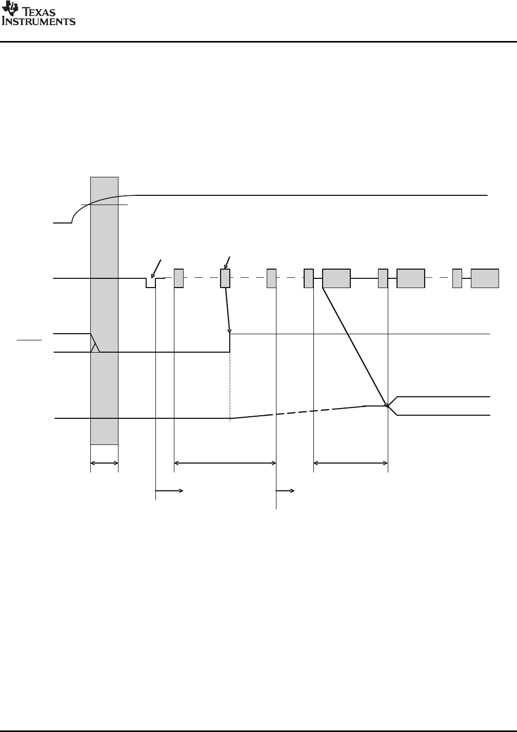
The PCM2912 is ready for setup when the reset sequence has finished and the USB bus is attached. After a
connection has been established by setup, the PCM2912 is ready to accept USB audio data. While awaiting the
audio data (idle state), the analog output is set to bipolar zero (BPZ).
When receiving the audio data, the PCM2912 stores the first audio packet, which contained 1-ms audio data, into
the internal storage buffer. The PCM2912 starts playing the audio data when detecting the following Start of
Frame (SOF) packet.
Figure 33. Initial Sequence
Copyright © 2008, Texas Instruments Incorporated Submit Documentation Feedback 23
Product Folder Link(s): PCM2912