
Datasheet


Table Of Contents
- FEATURES
- APPLICATIONS
- DESCRIPTION
- ABSOLUTE MAXIMUM RATINGS
- RECOMMENDED OPERATING CONDITIONS
- ELECTRICAL CHARACTERISTICS
- DEVICE INFORMATION
- TYPICAL PERFORMANCE CURVES OF INTERNAL FILTER
- TYPICAL PERFORMANCE CURVES
www.ti.com
Device Configuration
Standard AudioControlinterface(IF#0)
Endpoint#0
Endpoint#1
(IF#1)
IT
TID3
FU
UID5
Analog out
Analog in
Default endpoint
Audiostreaminginterface
Endpoint#2
(IF#2)
Audio streaminginterface
F U
UID2
F U
UID8
S
UID4
OT
TIDB
OT
TID6
IT
TID1
IT
TID7
UIDA
S
Interface #0
PCM2912
SLES216 – FEBRUARY 2008
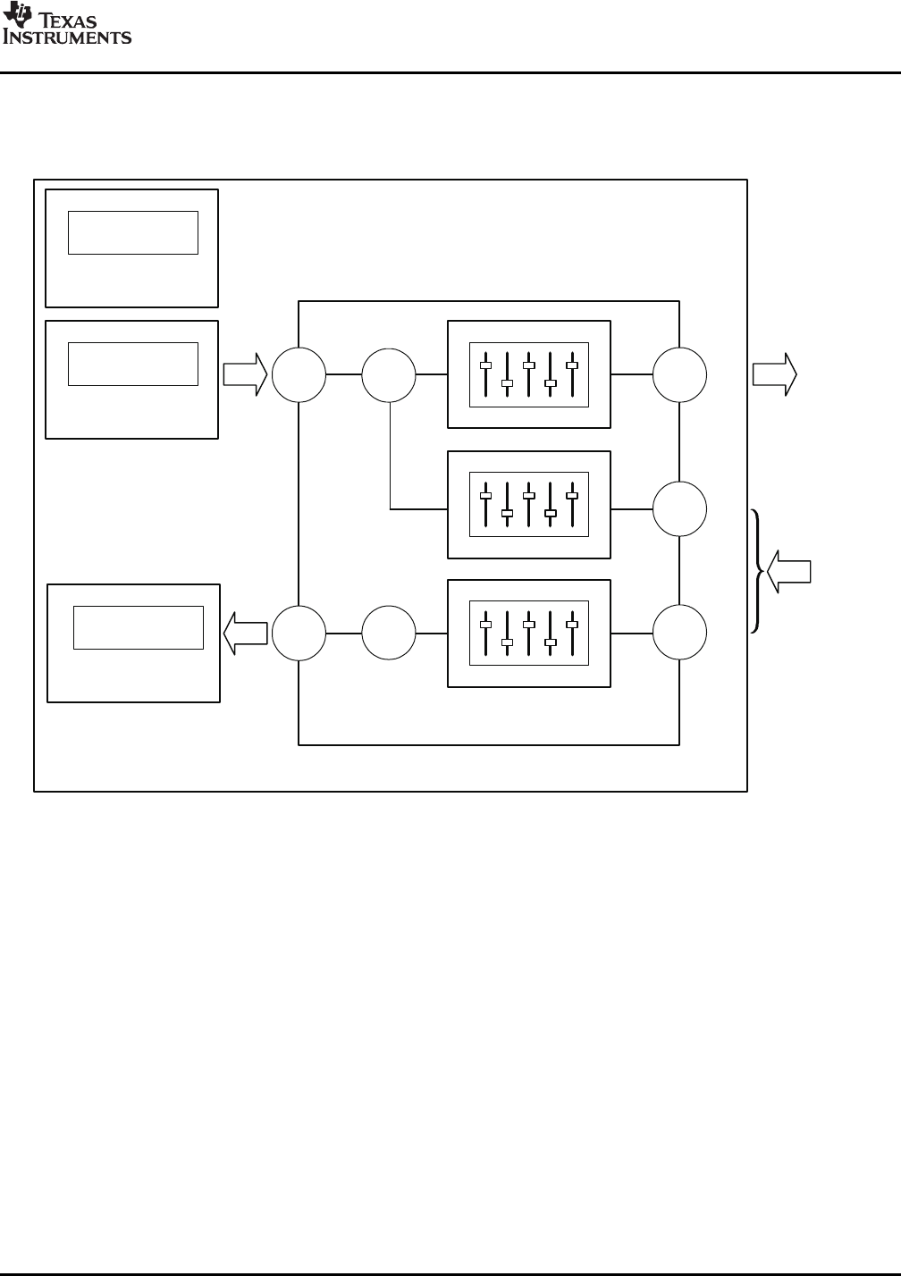
Figure 31 illustrates USB audio function topology. The PCM2912 has three interfaces. Each interface is
constructed by some alternative settings.
Figure 31. USB Audio Function Topology
Interface #0 is for control interface. Alternative setting #0 is the only possible setting for interface #0. Alternative
setting #0 describes the standard audio control interface. Audio control interface is constructed by a terminal.
The PCM2912 has ten terminals as follows.
• Input Terminal (Terminal ID#1) for audio analog input for sidetone
• Feature Unit (Unit ID#2) for sidetone PGA
• Input Terminal (Terminal ID#3) for isochronous-out stream
• Mixer Unit (Unit ID#4) for sidetone mixing
• Feature Unit (Unit ID#5) for analog output PGA
• Output Terminal (Terminal ID#6) for audio analog output
• Input Terminal (Terminal ID#7) for audio analog input
• Feature Unit (Unit ID#8) for analog input PGA
• Mixer Unit (Unit ID#A) for analog input
• Output Terminal (Terminal ID#B) for isochronous-in stream
Copyright © 2008, Texas Instruments Incorporated Submit Documentation Feedback 19
Product Folder Link(s): PCM2912