
Datasheet


Table Of Contents
- FEATURES
- APPLICATIONS
- DESCRIPTION
- ABSOLUTE MAXIMUM RATINGS
- RECOMMENDED OPERATING CONDITIONS
- ELECTRICAL CHARACTERISTICS
- PIN ASSIGNMENTS
- TYPICAL CHARACTERISTICS: INTERNAL FILTER
- TYPICAL CHARACTERISTICS
- GENERAL DESCRIPTION
INTERFACE SEQUENCE
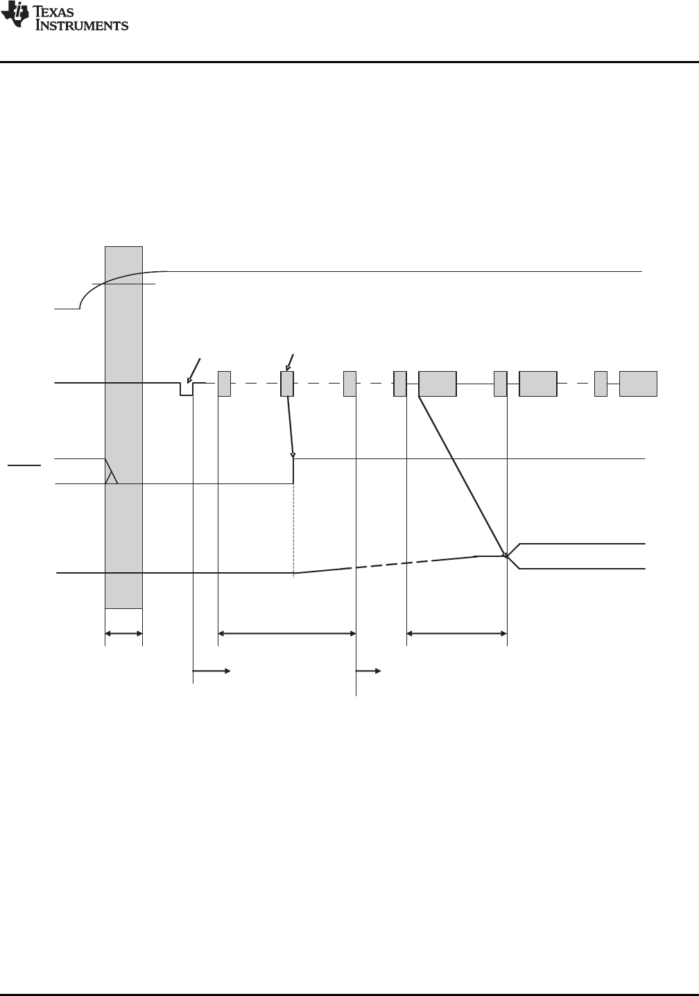
Power-On, Attach, and Play Back Sequence
D+(pin4),
D (pin3)-
0V
BusIdle
V (pin2)
BUS
SSPND (pin29)
V L (pin18),
V R(pin22)
OUT
OUT
BusReset SetConfiguration
1st AudioData 2nd AudioData
5.0V(typ)
2.5V(typ)
SOF SOF SOF
1ms
DeviceSetup
ReadyforSetup ReadyforPlayback
InternalReset
700 sm
PCM2912A
www.ti.com
.......................................................................................................................................................................................... SLES230 – SEPTEMBER 2008
The PCM2912A is ready for setup when the reset sequence has finished and the USB bus is attached. After a
connection has been established, the PCM2912A is ready to accept USB audio data. While waiting for the audio
data (that is, in an idle state), the analog output is set to bipolar zero (BPZ).
When receiving the audio data, the PCM2912A stores the first audio packet, which contains 1-ms audio data,
into the internal storage buffer. The PCM2912A starts playing the audio data when the subsequent Start of
Frame (SOF) packet is detected, as shown in Figure 33 .
Figure 33. Initial Sequence
Copyright © 2008, Texas Instruments Incorporated Submit Documentation Feedback 23
Product Folder Link(s): PCM2912A