
Datasheet


Table Of Contents
- FEATURES
- APPLICATIONS
- DESCRIPTION
- ABSOLUTE MAXIMUM RATINGS
- RECOMMENDED OPERATING CONDITIONS
- ELECTRICAL CHARACTERISTICS
- PIN ASSIGNMENTS
- TYPICAL CHARACTERISTICS: INTERNAL FILTER
- TYPICAL CHARACTERISTICS
- GENERAL DESCRIPTION
Microphone Amplifier
Input PGA
Sidetone Programmable Attenuator
Output Programmable Attenuator
V
COM1
and V
CCM2
Filter Pins
DAC
V
COM
10kW
20kW
FR/FL
C
F
SideTone
–
+
20kW
10kW
PCM2912A
SLES230 – SEPTEMBER 2008 ..........................................................................................................................................................................................
www.ti.com
The PCM2912A has a low-noise, single-ended, mono microphone amplifier with a mute function that is controlled
by MUTE (pin 30). The signal gain is selectable by MAMP (pin 23). The noise level at the input node is 5 µ V
RMS
,
and the input impedance is 20 k Ω .
The PCM2912A also has a low-noise input, programmable gain amplifier (PGA) for the microphone amplifier
output/ADC input, with a gain range of +30 dB to – 12 dB in 1dB/step.
The PCM2912A has a low-noise, sidetone programmable attenuator with a mute function for the sidetone signal
path (microphone amplifier output to output PGA input), and a gain range of 0 dB to – 76 dB in 1 dB/step.
The PCM2912A has a low-noise output programmable attenuator with a mute function for mixed signal, which
affects DAC output signal and sidetone signal. The output PGA gain range is 0 dB to – 76 dB in 1 dB/step.
V
COM2
(pin 12) is provided for the center voltage of the headphone amplifier. V
COM1
(pin 11) is provided for the
center voltage of all other analog circuits. Each V
COM
pin must be decoupled with an appropriate capacitor.
Because the headphone output is disconnected when entering the suspend state, determining the capacitance is
important to prevent pop noise, especially for V
COM2
(pin 12). The equivalent resistance of V
COM2
is 500 k Ω , and
V
COM1
is 15 k Ω .
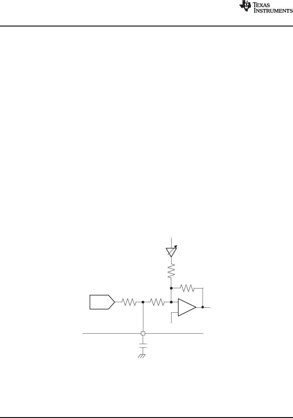
FL (pin 9) and FR (pin 10) are provided to make a low-pass filter (LPF) to decrease the DAC outband noise, as
shown in Figure 32 . This filter is optional.
Figure 32. Filter Circuit
22 Submit Documentation Feedback Copyright © 2008, Texas Instruments Incorporated
Product Folder Link(s): PCM2912A