
Datasheet


OPA567
SBOS287A
13
www.ti.com
APPLICATIONS INFORMATION
BASIC CONFIGURATION
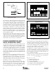
Figure 1 shows the OPA567 connected as a basic non-
inverting amplifier. However, the OPA567 can be used in
virtually any op amp configuration. A current limit setting
resistor (R
SET
, in Figure 1) is essential to the OPA567
operation, and cannot be omitted.
Power-supply terminals should be bypassed with low series
impedance capacitors. Using larger tantalum and smaller
ceramic type capacitors in parallel is recommended. Power-
supply wiring should have low series impedance.
POWER SUPPLIES
The OPA567 operates with excellent performance from a
single (+2.7V to +5.5V) supply or from dual supplies. Power
supply voltages do not need to be equal as long as the total
voltage remains below 5.5V. Parameters that vary signifi-
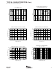
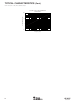
cantly with operating voltage are shown in the
Typical
Characteristics
section.
ADJUSTABLE CURRENT LIMIT AND CURRENT
LIMIT FLAG PIN
The OPA567 provides over-current protection to the load
through its accurate, user-adjustable current limit (pin 6). The
current limit value, I
LIMIT
, can be set from 0.2A to 2.2A by
controlling the current to the I
SET
pin. The current limit, I
LIMIT
,
will be 9800 • I
SET
, where I
SET
is the current through the I
SET
pin. Setting the current limit requires no special power
resistors. The output current does not flow through this pin.
Setting the current limit
As illustrated in Figure 2, the simplest method of setting the
current limit is to connect a resistor or potentiometer between
FIGURE 1. Basic Connections.
FIGURE 2. Setting the Current Limit—Resistor Method.
the I
SET
pin and V–, the negative supply, according to the
formula:
I
LIMIT
= 9800 • (1.18V/R
SET
)
Alternatively, the output current limit can be set by applying
a voltage source in series with a resistance using the equa-
tion:
I
LIMIT
= 9800 • [(1.18V – V
ADJUST
)/R
SET
]
The voltage source must be referenced to V–.
V
IN
R
1
R
2
47µF
Enable
(2)
47µF
0.1µF
I
SET
47µF
1, 12
2, 3
8
9
11
6
4, 5
0.1µF
R
SET
(Ω)I
LIMIT
(A)
23.2k
11.5k
7.68k
5.76k
0.5
1.0
1.5
2.0
R
SET
(1)
V+
NOTES: (1) R
SET
sets the current
limit value from 0.2A to 2.2A.
R
SET
can be a potentiometer to
easily adjust current limit and
calibrate out errors at the current
limit node. (2) Enable—pull Low
to disable output.
V
O
V–
OPA567
R
SET
V
ADJUST
(1)
(b) Resistor/Voltage Source Method
NOTE: (1) This voltage source must be able to
sink the current from the I
SET
pin, which is I
LIMIT
/9800.
1.18V
V–
I
LIMIT
= 9800 (1.18V – V
ADJUST
)
R
SET
I
SET
I
SET
8
9
6
2, 3 2, 3
4, 5
8
9
6
4, 5
R
POT
(a) Resistor or Potentiometer Method
Putting a set resistor in series with the potentiometer
will prevent potential short-circuit on pin.
1.18V
V–
I
LIMIT
= 9800 (1.18V/R
SET
)