
Datasheet


OPA3690
www.ti.com
SBOS237G –MARCH 2002–REVISED MARCH 2010
THERMAL ANALYSIS Note that it is the power in the output stage and not
into the load that determines internal power
Due to the high output power capability of the
dissipation.
OPA3690, heatsinking or forced airflow may be
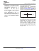
required under extreme operating conditions. As a worst-case example, compute the maximum T
J
Maximum desired junction temperature will set the using an OPA3690IDBQ in the circuit of Figure 36
maximum allowed internal power dissipation as operating at the maximum specified ambient
described below. In no case should the maximum temperature of +85°C and driving a grounded 100Ω.
junction temperature be allowed to exceed 175°C.
P
D
= 10V × 18.6mA + 3 [5
2
/(4 × (100Ω || 804Ω))
Operating junction temperature (T
J
) is given by:
P
D
= 397mW
T
A
+ P
D
× q
JA
Maximum T
J
= +85°C + (0.40W × 100°C/W)
The total internal power dissipation (P
D
) is the sum of
T
J
= 125°C
quiescent power (P
DQ
) and additional power
dissipated in the output stage (P
DL
) to deliver load
This worst-case condition is still well within rated
power. Quiescent power is simply the specified
maximum T
J
for this 100Ω load. Heavier loads may,
no-load supply current times the total supply voltage
however, exceed the 150°C maximum junction
across the part. P
DL
depends on the required output
temperature rating. Careful attention to internal power
signal and load but, for a grounded resistive load, is
dissipation is required and perhaps airflow considered
at a maximum when the output is fixed at a voltage
under extreme conditions.
equal to 1/2 of either supply voltage (for equal bipolar
supplies). Under this condition, P
DL
= V
S2
/(4 × R
L
)
where R
L
includes feedback network loading.
Copyright © 2002–2010, Texas Instruments Incorporated Submit Documentation Feedback 27
Product Folder Link(s): OPA3690