
User manual


www.ti.com
1.2.2 Core Frequency Flexibility
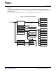
Device Clocking
The core frequency domain clocks are supplied by the PLL controller 1 (PLLC1). These domain clocks are
flexible, to a degree, within the limitations specified in the device-specific data manual. All of the following
frequency ranges and multiplier/divider ratios in the data manual must be adhered to:
• Input clock frequency range (MXI/CLKIN)
• PLL1 multiplier (PLLM) range
• PLL1 output (PLLOUT) frequency range based on the core voltage (1.05V or 1.2V) of the device
• Maximum device speed
• PLLC1's SYSCLK3:SYSCLK2:SYSCLK1 frequency ratio must be fixed to 1:3:6. For example, if
SYSCLK1 is at 600 MHZ, SYSCLK2 must be at 200 MHZ, and SYSCLK3 must be at 100 MHZ.
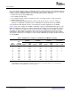
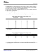
As specified in the data manual, the PLLs can be driven by any input ranging from 15 to 30 MHZ.
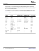
Table 2 shows some example PLL1 multiplier and divider settings assuming MXI/CLKIN frequency of 25
MHZ. The Applicable to Device Core Voltage column indicates whether the setting is allowed for a given
device core voltage. For example, the last row in Table 2 (PLL1 multiplier 24 for a 25 MHZ clock input)
only applies to devices with a core voltage 1.2V to meet the PLL1 output (PLLOUT) frequency range
required in the data manual. In addition, you must ensure the SYSCLK1 frequency does not exceed the
speed grade of the device. For example, for a device rated at 400 MHZ speed grade, SYSCLK1 must not
exceed 400 MHZ.
Table 2. Example PLL1 Frequencies and Dividers (25 MHZ Clock Input)
CLKDIV1 Domain CLKDIV3 Domain CLKDIV6 Domain Applicable to Device
(SYSCLK1) (SYSCLK2) (SYSCLK3) Core Voltage
PLL1
PLL1 PLLOUT Freq Freq Freq
Multiplier Freq (MHZ) Divider
(1)
(MHZ) Divider
(1)
(MHZ) Divider
(1)
(MHZ) 1.2V 1.05V
16 400.0 1 400.0 3 133.3 6 66.7 Y Y
17 425.0 1 425.0 3 141.7 6 70.8 Y Y
18 450.0 1 450.0 3 150.0 6 75.0 Y Y
19 475.0 1 475.0 3 158.3 6 79.2 Y Y
20 500.0 1 500.0 3 166.7 6 83.3 Y Y
21 525.0 1 525.0 3 175.0 6 87.5 Y -
22 550.0 1 550.0 3 183.3 6 91.7 Y -
23 575.0 1 575.0 3 191.7 6 95.8 Y -
24 600.0 1 600.0 3 200.0 6 100.0 Y
24 600.0 2 300.0 6 100.0 12 50.0 Y -
(1)
The RATIO bit in PLLDIV n is programmed as Divider - 1. For example, for a SYSCLK1 divider of 1, you should program
PLLDIV1.RATIO = 0, PLLDIV2.RATIO = 2, PLLDIV3.RATIO = 5.
8 Phase-Locked Loop Controller (PLLC) SPRUES0B – December 2007
Submit Documentation Feedback