
User manual

www.ti.com
2.6 Initialization
2.7 Auto Negotiation
2.8 Serial Interface Width Configuration
2.9 Address Translation
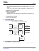
Peripheral Architecture
Since VLYNQ devices can be controlled solely over the serial interface (that is, no local CPU exists), an
automatic reliable initialization sequence (without user configuration) establishes a connection between
two VLYNQ devices, just after a VLYNQ module is enabled and auto-negotiation occurs. Auto-negotiation
is defined in Section 2.7 . The same sequence is used to recover from error conditions.
Bit 0 in the VLYNQ status register (LINK bit) is set to 1 when a link is established.
A link pulse timer generates a periodic link code every 2048 serial clock cycles. The link is lost when time
expires and no link code has been detected during a period of 4096 serial clock cycles.
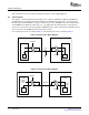
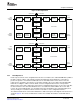
Auto-negotiation occurs after reset. It involves placing a negotiation protocol in the outbound data and
processing the inbound data to establish connection information. The width of the data pins on the serial
interface is automatically determined at reset as a part of the initialization sequence. For a connection
between two VLYNQ devices of version 2.0 and later (VLYNQ on the device is version 2.6), the
negotiation protocol using the available serial pins is used to convey the maximum width capability of each
device. The TXD data pins are not required to have the same width as the RXD data pins.
The auto width negotiation does not occur until after completion of the VLYNQ 1.x legacy width
configuration, which involves a period of 2000 VLYNQ 1.x system clock cycles for connection to VLYNQ
1.x devices. After the VLYNQ 1.x has determined its width, it receives the VLYNQ2.x auto width
negotiation protocol. The VLYNQ 1.x device does not recognize this protocol and transmits error codes
over the serial interface. The received error codes allow the VLYNQ 2.x devices to determine how many
serial pins are valid on the connected VLYNQ 1.x device.
Once the width is established, VLYNQ further identifies the version (version 1.x or version 2.x ) of the
remote VLYNQ. This better determines the capabilities of the connected VLYNQ device. This is software
readable via the VLYNQ auto-negotiation register (AUTNGO), bit 16 (0 = Ver 1.x , 1 = Ver 2.x), after the
link has been established.
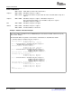
The VLYNQWD bit in the pin multiplexing register 0 (PINMUX0) controls the data width on the device,
thus allowing you to program the serial interface width (as shown in Table 2 ).
Table 2. Serial Interface Width
VLYNQWD VLYNQ Data Width
00 VLYNQ TXD[0] , VLYNQ RXD[0]
01 VLYNQ TXD[0:1] , VLYNQ RXD[0:1]
11 VLYNQ TXD[0:2] , VLYNQ RXD[0:2]
10 VLYNQ TXD[0:3] , VLYNQ RXD[0:3]
For detailed information on the processor pin multiplexing and configuration register, see the pin
multiplexing information in the device-specific data manual.
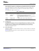
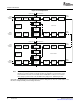
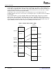
Remote VLYNQ device(s) are memory mapped to the local (host) device’s address space when a link is
established (this is similar to any other on-chip peripherals). Enumerating the VLYNQ devices (single or
multiple) into a coherent memory map for accessing each device is part of the initialization sequence.
After the enumeration, the host (local) device can access the remote device address map using local
device addresses. The VLYNQ module in the host device manages the address translation of the local
address to the remote address. A remote VLYNQ device is mapped to the local device’s address via the
address map registers (TX address map, RX address map size n, RX address map offset n, where n = 1
to 4). The transmit side has a contiguous map; the size of the map is the same as the remote device map.
Figure 7 illustrates this mapping.
SPRUF89 – October 2007 VLYNQ Port 17
Submit Documentation Feedback