
User manual


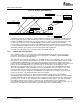
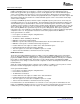
Table Of Contents
- Table of Contents
- Preface
- 1 Overview
- 2 SRIO Functional Description
- 3 Logical/Transport Error Handling and Logging
- 4 Interrupt Conditions
- 5 SRIO Registers
- 5.1 Introduction
- 5.2 Peripheral Identification Register (PID)
- 5.3 Peripheral Control Register (PCR)
- 5.4 Peripheral Settings Control Register (PER_SET_CNTL)
- 5.5 Peripheral Global Enable Register (GBL_EN)
- 5.6 Peripheral Global Enable Status Register (GBL_EN_STAT)
- 5.7 Block n Enable Register (BLKn_EN)
- 5.8 Block n Enable Status Register (BLKn_EN_STAT)
- 5.9 RapidIO DEVICEID1 Register (DEVICEID_REG1)
- 5.10 RapidIO DEVICEID2 Register (DEVICEID_REG2)
- 5.11 Packet Forwarding Register n for 16b DeviceIDs (PF_16B_CNTLn)
- 5.12 Packet Forwarding Register n for 8b DeviceIDs (PF_8B_CNTLn)
- 5.13 SERDES Receive Channel Configuration Registers n (SERDES_CFGRXn_CNTL)
- 5.14 SERDES Transmit Channel Configuration Registers n (SERDES_CFGTXn_CNTL)
- 5.15 SERDES Macro Configuration Register n (SERDES_CFGn_CNTL)
- 5.16 DOORBELLn Interrupt Status Register (DOORBELLn_ICSR)
- 5.17 DOORBELLn Interrupt Clear Register (DOORBELLn_ICCR)
- 5.18 RX CPPI Interrupt Status Register (RX_CPPI_ICSR)
- 5.19 RX CPPI Interrupt Clear Register (RX_CPPI_ICCR)
- 5.20 TX CPPI Interrupt Status Register (TX_CPPI_ICSR)
- 5.21 TX CPPI Interrupt Clear Register (TX_CPPI_ICCR)
- 5.22 LSU Status Interrupt Register (LSU_ICSR)
- 5.23 LSU Clear Interrupt Register (LSU _ICCR)
- 5.24 Error, Reset, and Special Event Status Interrupt Register (ERR_RST_EVNT_ICSR)
- 5.25 Error, Reset, and Special Event Clear Interrupt Register (ERR_RST_EVNT_ICCR)
- 5.26 DOORBELLn Interrupt Condition Routing Register (DOORBELLn_ICRR)
- 5.27 DOORBELLn Interrupt Condition Routing Register 2 (DOORBELLn_ICRR2)
- 5.28 RX CPPI Interrupt Condition Routing Register (RX_CPPI _ICRR)
- 5.29 RX CPPI Interrupt Condition Routing Register (RX_CPPI _ICRR2)
- 5.30 TX CPPI Interrupt Condition Routing Register (TX_CPPI _ICRR)
- 5.31 TX CPPI Interrupt Condition Routing Register (TX_CPPI _ICRR2)
- 5.32 LSU Module Interrupt Condition Routing Register 0 (LSU_ICRR0)
- 5.33 LSU Module Interrupt Condition Routing Register 1 (LSU_ICRR1)
- 5.34 LSU Module Interrupt Condition Routing Register 2 (LSU_ICRR2)
- 5.35 LSU Module Interrupt Condition Routing Register 3 (LSU_ICRR3)
- 5.36 Error, Reset, and Special Event Interrupt Condition Routing Register (ERR_RST_EVNT_ICRR)
- 5.37 Error, Reset, and Special Event Interrupt Condition Routing Register 2 (ERR_RST_EVNT_ICRR2)
- 5.38 Error, Reset, and Special Event Interrupt Condition Routing Register 3 (ERR_RST_EVNT_ICRR3)
- 5.39 INTDSTn Interrupt Status Decode Registers (INTDSTn_DECODE)
- 5.40 INTDSTn Interrupt Rate Control Registers (INTDSTn_RATE_CNTL)
- 5.41 LSUn Control Register 0 (LSUn_REG0)
- 5.42 LSUn Control Register 1 (LSUn_REG1)
- 5.43 LSUn Control Register 2 (LSUn_REG2)
- 5.44 LSUn Control Register 3 (LSUn_REG3)
- 5.45 LSUn Control Register 4 (LSUn_REG4)
- 5.46 LSUn Control Register 5 (LSUn_REG5)
- 5.47 LSUn Control Register 6 (LSUn_REG6)
- 5.48 LSU Congestion Control Flow Mask n (LSU_FLOW_MASKS n)
- 5.49 Queue Transmit DMA Head Descriptor Pointer Registers (QUEUEn_TXDMA_HDP)
- 5.50 Queue Transmit DMA Completion Pointer Registers (QUEUEn_TXDMA_CP)
- 5.51 Queue Receive DMA Head Descriptor Pointer Registers (QUEUEn_RXDMA_HDP)
- 5.52 Queue Receive DMA Completion Pointer Registers (QUEUEn_RXDMA_CP)
- 5.53 Transmit Queue Teardown Register (TX_QUEUE_TEAR_DOWN)
- 5.54 Transmit CPPI Supported Flow Mask Registers n (TX_CPPI_FLOW_MASKSn)
- 5.55 Receive Queue Teardown Register (RX_QUEUE_TEAR_DOWN)
- 5.56 Receive CPPI Control Register (RX_CPPI_CNTL)
- 5.57 Transmit CPPI Weighted Round Robin Control Register 0 (TX_QUEUE_CNTL0)
- 5.58 Transmit CPPI Weighted Round Robin Control Register 1 (TX_QUEUE_CNTL1)
- 5.59 Transmit CPPI Weighted Round Robin Control Register 2 (TX_QUEUE_CNTL2)
- 5.60 Transmit CPPI Weighted Round Robin Control Register 3 (TX_QUEUE_CNTL3)
- 5.61 Mailbox-to-Queue Mapping Register Ln (RXU_MAP_Ln)
- 5.62 Mailbox-to-Queue Mapping Register Hn (RXU_MAP_Hn)
- 5.63 Flow Control Table Entry Registers (FLOW_CNTLn)
- 5.64 Device Identity CAR (DEV_ID)
- 5.65 Device Information CAR (DEV_INFO)
- 5.66 Assembly Identity CAR (ASBLY_ID)
- 5.67 Assembly Information CAR (ASBLY_INFO)
- 5.68 Processing Element Features CAR (PE_FEAT)
- 5.69 Source Operations CAR (SRC_OP)
- 5.70 Destination Operations CAR (DEST_OP)
- 5.71 Processing Element Logical Layer Control CSR (PE_LL_CTL)
- 5.72 Local Configuration Space Base Address 0 CSR (LCL_CFG_HBAR)
- 5.73 Local Configuration Space Base Address 1 CSR (LCL_CFG_BAR)
- 5.74 Base Device ID CSR (BASE_ID)
- 5.75 Host Base Device ID Lock CSR (HOST_BASE_ID_LOCK)
- 5.76 Component Tag CSR (COMP_TAG)
- 5.77 1x/4x LP_Serial Port Maintenance Block Header Register (SP_MB_HEAD)
- 5.78 Port Link Time-Out Control CSR (SP_LT_CTL)
- 5.79 Port Response Time-Out Control CSR (SP_RT_CTL)
- 5.80 Port General Control CSR (SP_GEN_CTL)
- 5.81 Port Link Maintenance Request CSR n (SPn_LM_REQ)
- 5.82 Port Link Maintenance Response CSR n (SPn_LM_RESP)
- 5.83 Port Local AckID Status CSR n (SPn_ACKID_STAT)
- 5.84 Port Error and Status CSR n (SPn_ERR_STAT)
- 5.85 Port Control CSR n (SPn_CTL)
- 5.86 Error Reporting Block Header (ERR_RPT_BH)
- 5.87 Logical/Transport Layer Error Detect CSR (ERR_DET)
- 5.88 Logical/Transport Layer Error Enable CSR (ERR_EN)
- 5.89 Logical/Transport Layer High Address Capture CSR (H_ADDR_CAPT)
- 5.90 Logical/Transport Layer Address Capture CSR (ADDR_CAPT)
- 5.91 Logical/Transport Layer Device ID Capture CSR (ID_CAPT)
- 5.92 Logical/Transport Layer Control Capture CSR (CTRL_CAPT)
- 5.93 Port-Write Target Device ID CSR (PW_TGT_ID)
- 5.94 Port Error Detect CSR n (SPn_ERR_DET)
- 5.95 Port Error Rate Enable CSR n (SPn_RATE_EN)
- 5.96 Port n Attributes Error Capture CSR 0 (SPn_ERR_ATTR_CAPT_DBG0)
- 5.97 Port n Packet/Control Symbol Error Capture CSR 1 (SPn_ERR_CAPT_DBG1)
- 5.98 Port n Packet/Control Symbol Error Capture CSR 2 (SPn_ERR_CAPT_DBG2)
- 5.99 Port n Packet/Control Symbol Error Capture CSR 3 (SPn_ERR_CAPT_DBG3)
- 5.100 Port n Packet/Control Symbol Error Capture CSR 4 (SPn_ERR_CAPT_DBG4)
- 5.101 Port Error Rate CSR n (SPn_ERR_RATE)
- 5.102 Port Error Rate Threshold CSR n (SPn_ERR_THRESH)
- 5.103 Port IP Discovery Timer in 4x mode (SP_IP_DISCOVERY_TIMER)
- 5.104 Port IP Mode CSR (SP_IP_MODE)
- 5.105 Serial Port IP Prescalar (IP_PRESCAL)
- 5.106 Port-Write-In Capture CSR n (SP_IP_PW_IN_CAPTn)
- 5.107 Port Reset Option CSR n (SPn_RST_OPT)
- 5.108 Port Control Independent Register n (SPn_CTL_INDEP)
- 5.109 Port Silence Timer n (SPn_SILENCE_TIMER)
- 5.110 Port Multicast-Event Control Symbol Request Register n (SPn_MULT_EVNT_CS)
- 5.111 Port Control Symbol Transmit n (SPn_CS_TX)
www.ti.com
LSU_Reg0 RapidIO Address MSB Control
31
RapidIO Address LSB/Config_offset Control
31 0
LSU_Reg1
DSP Address Control
31 0
LSU_Reg2
RSV Control
31 0
LSU_Reg3
12 11
Byte_count
OutPortID Control
31 0
LSU_Reg4
1
7
Interrupt Req
30
Priority
29 28
xambs
27 26
ID Size
25 24
DestID
23 8
RSV
Drbll Info Command
31 0
LSU_Reg5
8 7
Packet Type
16
Hop Count
15
RSV
31
LSU_Reg6
1
Bsy
5
Completion Code
4
Status
0
0
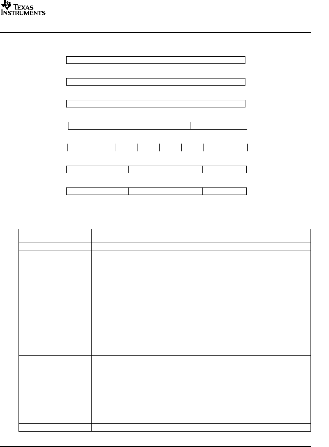
SRIO Functional Description
Figure 10. Load/Store Registers for RapidIO (Address Offset: LSU1 0x400-0x418, LSU2 0x420-0x438,
LSU3 0x440-0x458, LSU4 0x460-0x478)
Mapping of command register fields to RapidIO packet header fields is as follows:
Table 13. Control/Command Register Field Mapping
Control/Command Register RapidIO Packet Header Field
Field
RapidIO Address MSB 32b Ext Address Fields – Packet Types 2,5, and 6
RapidIO Address
1. 32b Address– Packet Types 2,5, and 6 (Will be used in conjunction with BYTE_COUNT to
LSB/Config_offset
create 64b aligned RapidIO packet header address)
2. 24b Config_offset Field – Maintenance Packets Type 8 (Will be used in conjunction with
BYTE_COUNT to create 64b aligned RapidIO packet header Config_offset). The 2 LSB of
this field must be zero since the smallest configuration access is 4B.
DSP Address 32b DSP byte address. Not available in RapidIO Header.
Byte_Count Number of data bytes to Read/Write - up to 4KB. (Used in conjunction with RapidIO address to
create WRSIZE/RDSIZE and WDPTR in RapidIO packet header.)
000000000000b – 4KB
000000000001b – 1B
000000000010b – 2B
. . .
111111111111b – 4095B
(Maintenance requests are limited to 4B)
ID Size RapidIO tt field specifying 8- or 16-bit DeviceIDs.
00b – 8b deviceIDs
01b – 16b deviceIDs
10b - reserved
11b - reserved
Priority RapidIO prio field specifying packet priority (0 = lowest, 3 = highest). Request packets should not
be sent at a priority level of 3 to avoid system deadlock. It is the responsibility of the software to
assign the appropriate outgoing priority.
Xambs RapidIO xambs field specifying extended address MSB.
DestID RapidIO destinationID field specifying target device.
SPRU976 – March 2006 Serial RapidIO (SRIO) 33
Submit Documentation Feedback