
Datasheet


OA1
+
−
OA2
+
−
R2R1
V2
V1
OA0
+
−
R2R1
(V2 − V1) × R2
R1
Vdiff =
OA Operation
www.ti.com
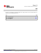
Figure 20-4 shows an example of a three-opamp differential amplifier using OA0, OA1 and OA2 (Three
opamps are not available on all devices. See device-specific data sheet for implementation.). The control
register settings are shown in Table 20-5. The gain for the amplifier is selected by the OAFBRx bits of
OA0 and OA2. The OAFBRx settings for both OA0 and OA2 must be equal. The gain settings are shown
in Table 20-6. The OAx interconnections are shown in Figure 20-5.
Table 20-5. Three-Opamp Differential Amplifier Control
Register Settings
Settings
Register
(binary)
OA0CTL0 xx xx xx 0 0
OA0CTL1 xxx 001 0 x
OA1CTL0 xx xx xx 0 0
OA1CTL1 000 111 0 x
OA2CTL0 11 11 xx x x
OA2CTL1 xxx 110 0 x
Table 20-6. Three-Opamp Differential Amplifier Gain
Settings
OA0/OA2 OAFBRx Gain
000 0
001 1/3
010 1
011 1 2/3
100 3
101 4 1/3
110 7
111 15
Figure 20-4. Three-Opamp Differential Amplifier
518
OA SLAU144J–December 2004–Revised July 2013
Submit Documentation Feedback
Copyright © 2004–2013, Texas Instruments Incorporated