MSP-EXP430G2 LaunchPad Experimenter Board User's Guide Literature Number: SLAU318C July 2010 – Revised August 2012
Contents Preface ....................................................................................................................................... 4 1 MSP-EXP430G2 LaunchPad Overview ................................................................................... 5 6 7 .................................................................................................................. 5 ..............................................................................................................
www.ti.com List of Figures 1 MSP-EXP430G2 LaunchPad Overview .................................................................................. 6 2 Insert Device Into Target Socket .......................................................................................... 9 3 Code Composer Studio™ v4 in Debugging Mode .................................................................... 10 4 MSP-EXP430G2 LaunchPad With Attached eZ430-RF2500 Target Board .......................................
Preface SLAU318C – July 2010 – Revised August 2012 Read This First If You Need Assistance If you have any feedback or questions, support for the MSP430™ devices and the MSP-EXP430G2 is provided by the Texas Instruments Product Information Center (PIC) and the TI E2E Forum (https://community.ti.com/forums/12.aspx). Contact information for the PIC can be found on the TI web site at http://support.ti.com. Additional device-specific information can be found on the MSP430 web site at http://www.ti.com/msp430.
User's Guide SLAU318C – July 2010 – Revised August 2012 MSP-EXP430G2 LaunchPad Experimenter Board 1 MSP-EXP430G2 LaunchPad Overview 1.1 Overview The MSP-EXP430G2 low-cost experimenter board called LaunchPad is a complete development solution for the Texas Instruments MSP430G2xx Value Line series. The integrated USB-based emulator offers all the hardware and software necessary to develop applications for all MSP430G2xx series devices.
MSP-EXP430G2 LaunchPad Overview www.ti.com Figure 1. MSP-EXP430G2 LaunchPad Overview For latest information on the MSP-EXP430G2 LaunchPad and all the necessary files, visit the MSP430 LaunchPad Wiki page http://processors.wiki.ti.com/index.php/MSP430_LaunchPad_(MSP-EXP430G2). There you can find software examples, more details on the supported software, and where to order the MSP-EXP430G2 LaunchPad. 1.
Installation www.ti.com 1.3 Revisions The first production revision of the LaunchPad in 2010 was 1.3. In 2012 the LaunchPad board revision changed from 1.4 to 1.5 to align with the new release of Value Line devices. The differences in the schematic and the kit contents are: • Layout and Schematic: – Voltage feedback in the emulator changed to increase startup stability (Rev 1.3 to Rev 1.
Getting Started With MSP-EXP430G2 LaunchPad 3 Getting Started With MSP-EXP430G2 LaunchPad 3.1 Getting Started www.ti.com The first time the MSP-EXP430G2 LaunchPad Experimenter Board is used, a demo application automatically starts as soon as the board is powered from the USB host. To start the demo, connect the MSP-EXP430G2 LaunchPad with the included mini USB cable to a free USB port. The demo application starts with an LED toggle to show the device is active.
Develop an Application With the MSP-EXP430G2 LaunchPad www.ti.com 4 Develop an Application With the MSP-EXP430G2 LaunchPad 4.1 Developing an Application The integrated development environments (IDEs) shown in Section 2 offer support for the whole MSP430G2xx Value Line. The MSP-EXP430G2 LaunchPad needs only a connection to the USB of the Host PC—there is no external hardware required.
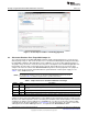
Develop an Application With the MSP-EXP430G2 LaunchPad www.ti.com Figure 3. Code Composer Studio™ v4 in Debugging Mode 4.3 Disconnect Emulator From Target With Jumper J3 The connection between the MSP-EXP430G2 emulator and the attached target device can be opened with the jumper array J3. This can be useful to access an attached eZ430 target board by disconnecting the Spi-Bi-Wire JTAG lines RST and TEST or if the JTAG lines are used for other application purposes.
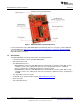
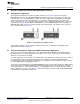
Develop an Application With the MSP-EXP430G2 LaunchPad www.ti.com 4.4 Program Connected eZ430 Target Boards The MSP-EXP430G2 LaunchPad can program the eZ430-RF2500T target boards, the eZ430-Chronos watch module, or the eZ430-F2012T/F2013T. To connect one of the ez430 targets, connector J4 must be populated with a 0.050-in (1.27-mm) pitch male header, as shown in Figure 4. Figure 4.
Develop an Application With the MSP-EXP430G2 LaunchPad 4.6 www.ti.com Connecting a Satellite Board The LaunchPad is the perfect experimenter board to start hardware development with the MSP430G2xx Value Line. Connectors J1 and J2 and the power supply at J6 are aligned in a 0.1-in (2.54-mm) grid to allow an easy and inexpensive development of a breadboard extension module. These satellite boards can access all the signals of the LaunchPad target device.
Develop an Application With the MSP-EXP430G2 LaunchPad www.ti.com Table 3. Supported Devices (continued) Part Number 4.
MSP-EXP430G2 Hardware www.ti.com 5 MSP-EXP430G2 Hardware 5.1 Device Pinout Figure 5.
Schematics 5.2 MSP-EXP430G2 Hardware www.ti.
RST3410 1u/6.3V C8 EZ_VCC R16 47k GND DNP BRXDI BTXDI CLK3410 SCL SDA R10 10k R11 15k R12 33k D1 1N4148 R19 3k3 R22 3k3 GND 1 9 12 2 22 17 19 10 11 32 31 30 29 27 26 VREGEN RESET WAKEUP SUSPEND CLKOUT U3 E1 SCL SDA WC 100n PUR DP DM CTS DSR DCD RI/CP RTS DTR TEST0 TEST1 VCC VCC1 VDD18 GND GND1 GND2 C11 100n 6 5 8 7 CAT24FC32UI VSS VCC E2 E0 U5 TUSB3410VF SIN SOUT SDA SCL P3.0 P3.1 P3.3 P3.
MSP-EXP430G2 Hardware www.ti.com 0R R29 DNP R28 XIN VCC GND XOUT P1.0 P1.6 J1 1 2 3 4 5 6 7 8 9 10 R34 47K VCC P1.0 P1.1 P1.2 P1.3 P1.4 P1.5 P2.0 P2.1 P2.2 20 19 18 17 16 15 14 13 12 11 RST/SBWTDIO 20 Pin Socket IC1 1 2 3 4 5 6 7 8 9 10 Socket: TBD Type: TBD S2 GND P1.3 20 19 18 17 16 15 14 13 12 11 J2 MSP-EXP430G2 TARGET SOCKET GND XIN XINR XOUTR XOUT TEST/SBWTCK RST/SBWTDIO P1.7 P1.6 P2.5 P2.4 P2.3 R27 GND 47K S1 1.
TP6TP4TP2 TP7TP5TP3TP1 GND GND GND C1 10n RESET R1 47k C2 16p EZ_VCC C3 16p Q1 12MHz 48 47 46 45 44 43 42 41 40 39 38 37 36 35 34 33 R2 47k GND R3 47k RST3410 BRXDI BTXDI URXD UTXD R4 R5 R6 R7 100R 100R 100R 100R CLK3410 EZ_VCC VCC TEST/SBWTCK RST/SBWTDIO P1.2 BRXD SBW & UART I/F to Argon 9 7 5 3 1 1 2 3 4 5 6 SL127L6TH J4 SBW & UART I/F to external Target J3 changed on Rev 1.5 EZ_VCC 10 SBWTCK 8 SBWTDIO 6 4 BTXD 2 P1.1 BRXD BTXD P1.1 VCC SBWTCK SBWTDIO GND P1.
MSP-EXP430G2 Hardware www.ti.com RST3410 1u/6.
R29 0R XIN VCC GND XOUT P1.0 P1.6 J1 1 2 3 4 5 6 7 8 9 10 DNP VCC P1.0 P1.1 P1.2 P1.3 P1.4 P1.5 P2.0 P2.1 P2.2 R34 47K GND 20 19 18 17 16 15 14 13 12 11 20 Pin Socket IC1 1 2 3 4 5 6 7 8 9 10 Socket: TBD Type: TBD R27 47K RST/SBWTDIO GND GND XIN XINR XOUTR XOUT TEST/SBWTCK RST/SBWTDIO P1.7 P1.6 P2.5 P2.4 P2.3 S1 GND 20 19 18 17 16 15 14 13 12 11 S2 P1.3 J2 MSP-EXP430G2 TARGET SOCKET 1.
MSP-EXP430G2 Hardware www.ti.com 5.3 PCB Layout Figure 12.
MSP-EXP430G2 Hardware www.ti.com Figure 13.
MSP-EXP430G2 Hardware www.ti.com Figure 14.
MSP-EXP430G2 Hardware 5.4 www.ti.com Bill of Materials (BOM) Table 5. Bill of Materials Ref Name Number per Board 1 C2, C3 2 16pF 0402 (33 pF on Rev 1.3) 2 C9, C10 2 22pF 0402 3 C1 1 10nF 0402 4 C5, C7, C11, C12, C13 5 100nF 0402 5 C4, C6, C8 3 1µF, 6.3V 0604 6 D1 1 1N4148 MicroMELF 7 EZ_USB 1 Mini-USB connector 8 Q1 1 SMD oscillator 12 MHz 9 R1, R2, R3, R16, R17 3 47k 0402 (R16, R17 is not populated) 10 R8 1 61k5 0402 (6k8 in Rev 1.
Suggested Reading www.ti.com 6 Suggested Reading The primary sources of MSP430™ information are the device-specific data sheets and the family user's guides. The most up-to-date versions of those documents can be found at the Texas Instruments MSP430 page or the MSP430 LaunchPad wiki. http://www.ti.com/msp430, http://processors.wiki.ti.com/index.
Frequently Asked Questions (FAQ) www.ti.com Experimenter Board and restarting the communicating application. Also make sure that all the jumpers on J3 are connected properly between the emulator and the target device. On revision 1.5 and newer, the orientation of the UART jumpers must align with the software implementation on the target device. 7. I soldered the 32-kHz crystal to the board and the oscillation is not starting.
EVALUATION BOARD/KIT/MODULE (EVM) ADDITIONAL TERMS Texas Instruments (TI) provides the enclosed Evaluation Board/Kit/Module (EVM) under the following conditions: The user assumes all responsibility and liability for proper and safe handling of the goods. Further, the user indemnifies TI from all claims arising from the handling or use of the goods.
FCC Interference Statement for Class B EVM devices This equipment has been tested and found to comply with the limits for a Class B digital device, pursuant to part 15 of the FCC Rules. These limits are designed to provide reasonable protection against harmful interference in a residential installation. This equipment generates, uses and can radiate radio frequency energy and, if not installed and used in accordance with the instructions, may cause harmful interference to radio communications.
【Important Notice for Users of this Product in Japan】 】 This development kit is NOT certified as Confirming to Technical Regulations of Radio Law of Japan If you use this product in Japan, you are required by Radio Law of Japan to follow the instructions below with respect to this product: 1. 2. 3. Use this product in a shielded room or any other test facility as defined in the notification #173 issued by Ministry of Internal Affairs and Communications on March 28, 2006, based on Sub-section 1.
EVALUATION BOARD/KIT/MODULE (EVM) WARNINGS, RESTRICTIONS AND DISCLAIMERS For Feasibility Evaluation Only, in Laboratory/Development Environments. Unless otherwise indicated, this EVM is not a finished electrical equipment and not intended for consumer use.
IMPORTANT NOTICE Texas Instruments Incorporated and its subsidiaries (TI) reserve the right to make corrections, enhancements, improvements and other changes to its semiconductor products and services per JESD46C and to discontinue any product or service per JESD48B. Buyers should obtain the latest relevant information before placing orders and should verify that such information is current and complete.