MSP-EXP430FR5969 LaunchPad™ Development Kit User's Guide Literature Number: SLAU535A February 2014 – Revised June 2014
Contents 1 2 3 Getting Started .................................................................................................................... 5 1.1 Introduction................................................................................................................ 5 1.2 Key Features.............................................................................................................. 6 1.3 Kit Contents .............................................................................
www.ti.com List of Figures 1 MSP-EXP430FR5969 ....................................................................................................... 5 2 EVM Overview 3 4 5 6 7 8 9 10 11 12 13 14 15 16 17 18 19 20 21 22 23 24 25 26 27 ............................................................................................................... 7 Block Diagram ................................................................................................................ 8 MSP430FR5969 Pinout ........
www.ti.com List of Tables 1 EnergyTrace++ Debug Windows ......................................................................................... 14 2 EnergyTrace™ Technology Control Bar Icons ......................................................................... 15 3 Isolation Block Connections............................................................................................... 16 4 Hardware Change Log.....................................................................................
User's Guide SLAU535A – February 2014 – Revised June 2014 MSP-EXP430FR5969 LaunchPad™ Development Kit User's Guide 1 Getting Started 1.1 Introduction MSP430™ ultra-low-power (ULP) MCUs with embedded Ferroelectric Random Access Memory (FRAM) technology now join the MCU LaunchPad™ Development Kit ecosystem. The MSP-EXP430FR5969 (or the "FR5969 LaunchPad") is an easy-to-use evaluation module (EVM) for the MSP430FR5969 microcontroller.
Getting Started www.ti.com Rapid prototyping is simplified by the 20-pin BoosterPack™ plug-in module headers, which support a wide range of available BoosterPacks. You can quickly add features like wireless connectivity, graphical displays, environmental sensing, and much more. You can either design your own BoosterPack or choose among many already available from TI and third-party developers.
Getting Started www.ti.com 1.5 Next Steps – Looking Into the Provided Code After the out-of-box demo, more features can be explored. The hardware features on the LaunchPad are shown in Section 2, and the provided code examples and how to use them are in Section 3. More details and documentation can be found at http://www.ti.com/tool/msp-exp430fr5969. Code is licensed under BSD and TI encourages reuse and modifications to fit your needs. 2 Hardware Figure 2 shows an overview of the LaunchPad hardware.
Hardware 2.1 www.ti.com Block Diagram Figure 3 shows the block diagram. Micro-B USB LED Red, Green ESD Protection Crystal 4 MHz Debug MCU 3.3-V LDO UART, SBW to Target Power to Target 14-pin JTAG header 100-mF SuperCap Power Selection Reset button Crystals HF (MHz) and 32.768 kHz Target Device MSP430FR5969 20-pin LaunchPad standard headers User Interface 2 buttons and 2 LEDs Figure 3. Block Diagram 2.
Hardware DVCC P2.7 P2.3/TA0.0/UCA1STE/A6/C10 P2.4/TA1.0/UCA1CLK/A7/C11 AVSS PJ.6/HFXIN PJ.7/HFXOUT AVSS PJ.4/LFXIN PJ.5/LFXOUT AVSS AVCC www.ti.com 48 47 46 45 44 43 42 41 40 39 38 37 P1.0/TA0.1/DMAE0/RTCCLK/A0/C0/VREF-/VeREF- 1 36 DVSS P1.1/TA0.2/TA1CLK/COUT/A1/C1/VREF+/VeREF+ 2 35 P4.6 P1.2/TA1.1/TA0CLK/COUT/A2/C2 3 34 P4.5 P3.0/A12/C12 4 33 P4.4/TB0.5 P3.1/A13/C13 5 32 P1.7/TB0.4/UCB0SOMI/UCB0SCL/TA1.0 P3.2/A14/C14 6 31 P1.6/TB0.3/UCB0SIMO/UCB0SDA/TA0.0 P3.
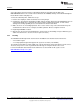
Hardware 2.2.1 www.ti.com Measure MSP430 Current Draw A specific jumper J9 is placed on the LaunchPad to allow for measuring current draw of the MSP430FR5969 device. The current measured includes the FR5969, and any current drawn through the BoosterPack headers and jumper J1. To measure ultra-low power, follow these steps: 1. Remove the J9 jumper; attach an ammeter across this jumper. 2. Consider the effect that the backchannel UART and any circuitry attached to the FR5969 may have on current draw.
Hardware www.ti.com 2.3 eZ-FET Onboard Emulator With EnergyTrace™ Technology To keep development easy and cost effective, TI's LaunchPad development tools integrate an onboard emulator, eliminating the need for expensive programmers. The FR5969 LaunchPad has the new eZ-FET emulator (see Figure 5), a simple and low-cost debugger that supports almost all MSP430 device derivatives. Figure 5. eZ-FET Emulator The eZ-FET provides many features that make debugging an easy experience.
Hardware 2.3.2 www.ti.com Application (or "Backchannel") UART The backchannel UART allows communication with the USB host that isn't part of the target application's main functionality. This is very useful during development, and also provides a communication channel to the PC host side. This can be used to create GUIs and other programs on the PC that communicate with the FR5969 LaunchPad. The pathway of the backchannel UART is shown in Figure 10.
Hardware www.ti.com 2.3.3 EnergyTrace™ Technology EnergyTrace™ Technology is an energy-based code analysis tool set that is useful for measuring and viewing the application’s energy profile and optimizing it for ultra-low power consumption. The MSP430FR5969 device supports EnergyTrace++ (EnergyTrace + [CPU State] + [Peripheral States]) for full access to the application energy profile as well as CPU and peripheral states. By default, EnergyTrace technology is disabled in CCS.
Hardware www.ti.com To fully enable the EnergyTrace++ setting, the ultra-low-power debug mode must be enabled. Right click on the active project in the project explorer and click Properties. In the Debug section, enable "Ultra Low Power debug/ Debug LPMx.5" option in the Low Power Mode Settings (see Figure 8). If this option is not enabled, the EnergyTrace++ mode cannot capture data from the device. Figure 8.
Hardware www.ti.com These tabs allow you to see exactly what is happening in your application, and find power black holes. An example application with the EnergyTrace++ windows is shown in Figure 9. Figure 9. Debug Session With EnergyTrace++ Windows After the EnergyTrace window is active, it can be controlled with the buttons in Table 2. Table 2. EnergyTrace™ Technology Control Bar Icons Enable or disable EnergyTrace Technology. When disabled, icon turns gray.
Hardware 2.3.4 www.ti.com Emulator Connection – Isolation Jumper Block The isolation jumper block at Jumper J13 allows the user to connect/disconnect signals that cross from the eZ-FET domain into the FR5969 target domain. This includes eZ-FET Spy-Bi-Wire signals, application UART signals, and 3V3 and 5V power (see Table 3).
Hardware www.ti.com 2.3.5 14-Pin JTAG Connector This EVM contains a footprint for TI's standard 14-pin MSP430 JTAG header. This connector can be used as needed. For debug purposes, this connector offers 4-wire JTAG compared to the 2-wire Spy-Bi-Wire from the eZ-FET. In certain use cases this can be advantageous. The MSP-FET or another MSP430 external debug tool such as MSP-FET430UIF or third-party tool can be used.
Hardware 2.4 www.ti.com Power The board is designed to support five different power scenarios. The board can be powered by the eZFET or JTAG debugger, external power, BoosterPack power, or standalone super cap power.
Hardware www.ti.com 2.4.1 eZ-FET USB Power The most common scenario is power from USB through the eZ-FET debugger. This provides 5-V power from USB and also regulates this power rail to 3.3 V for eZ-FET operation and 3.3 V to the target side of the LaunchPad. Power from the eZ-FET is controlled by jumper J13. For 3.3 V, ensure that a jumper is connected across the J13 "V+" terminal. The eZ-FET is a debugger, so J10 must be set to debugger for power to reach the target MSP430FR5969 device.
Hardware 2.4.3 www.ti.com External Power Supply An extra header J12 is present on the board to supply external power. When supplying external power, jumper J10 must be set to "External." It is important to understand the device voltage operation specifications when supplying external power. The MSP430FR5969 has an operating range of 1.8 V to 3.6 V. More information can be found in the device data sheet. For power configuration diagram, see Figure 13. 2.4.
Hardware www.ti.com 2.4.5 Super Cap A 100-mF (0.1-F) super cap is mounted onboard and allows powering the system without any external power. This highlights the ultra-low power of the MSP430FR5969 target device. See how long you can run your application on the super cap alone! 2.4.5.1 Charging the Super Cap To charge the super cap, jumper J11 is used. By default there is no jumper across J11. Place a jumper across J11 to charge the super cap.
Hardware www.ti.
Hardware www.ti.com While most BoosterPacks are compliant with the standard, some are not. The FR5969 LaunchPad is compatible with all 20-pin BoosterPacks that are compliant with the standard. If the reseller or owner of the BoosterPack does not explicitly indicate compatibility with the FR5969 LaunchPad, you should compare the schematic of the candidate BoosterPack with the LaunchPad to ensure compatibility.
Hardware 2.7 www.ti.com Hardware Change log Table 4 shows the hardware revision history. Table 4. Hardware Change Log PCB Revision 3 Description Rev 1.6 Initial Release Rev 2.0 Added EnergyTrace functionality, extended PCB dimensions, added mounting holes, updated isolation block order, added 5V BP pin, updated silkscreen Software Examples There are three software examples included with the FR5969 LaunchPad, which can be found in the zip source folder (SLAC645). Table 5 describes these examples.
Software Examples www.ti.com 3.2 Development Environment Requirements To use any of the below software examples with the MSP430FR5969 LaunchPad, you must have an integrated development environment (IDE) that supports the MSP430FR5969 device. Table 6. IDE Minimum Requirements for MSP430FR5969 Code Composer Studio™ IDE IAR Embedded Workbench™ IDE CCS v5.5 or later IAR EW430 v5.60 or later For more details on where to download the latest IDE, see Section 4.3. 3.2.
Software Examples 3.2.2 www.ti.com CCS CCS v5.5 or higher is required. When CCS has been launched, and a workspace directory chosen, use Project→Import Existing CCS Eclipse Project. Direct it to the desired demo's project directory containing main.c. This is one of the OutOfBox_FR5969, 430BOOST-SHARP96_ULP_FRAM, or 430BOOSTSHARP96_GrlibDisplay projects (see Figure 17). Figure 17. Directing the Project→Import Function to the Demo Project Selecting the \CCS or \CCS_Code_Size_Limited folder also works.
Software Examples www.ti.com Figure 18. When CCS Has Found the Project Sometimes CCS finds it but does not have a checkmark; this might mean that a project by that name is already in the workspace. Rename or delete that project to resolve this conflict. (Even if you don't see it in the CCS workspace, be sure to check the workspace's directory on the file system.) 3.2.3 IAR IAR Embedded Workbench™ IDE v5.60 or higher is required.
Software Examples 3.3.1 www.ti.com Source File Structure The project is organized in multiple files. This makes it easier to navigate and reuse parts of it for other projects. Table 7 describes each file in the project. Table 7. Source Files and Folders 3.3.2 Name Description main.c The out-of-box demo main function, initializations, shared ISR's, etc LiveTempMode.c Main function file for live temperature streaming mode FRAMLogMode.
Software Examples www.ti.com The MSP430FR5969 first sends two calibration constants for the temperature sensor to the PC GUI. It then sets up its 12-bit ADC for sampling and converting the signals from its internal temperature sensor. A hardware timer is also configured to trigger the ADC conversion every 0.125 seconds before the device enters low-power mode 3 to conserve power. As soon as the ADC sample and conversion is complete, the raw ADC data is sent the through the UART backchannel to the PC GUI.
Software Examples www.ti.com Each time the device wakes up, the green LED lights up to indicate its state to the user. The 12-bit ADC is set up to sample and convert the signals from its internal temperature sensor and battery monitor (Super Cap voltage). A section of the device's FRAM is allocated to store the raw ADC output data (address 0x9000 to 0xEFFF). This allows the demo to store up to 6144 temperature and voltage data points (5 seconds/sample is approximately 8.5 hours of data).
Software Examples www.ti.com 3.4.2 Navigation and Main Menu Upon powering up the demo, the title screens appear on the LCD, and are followed by the main selection menu. The main menu displays all the applications available in the demo. The application options in the menu are highlighted by using the left capacitive touch slider. NOTE: Only the left capacitive touch slider is activated for navigation. After an application is selected, the right button (S2) is used to enter the application.
Software Examples www.ti.com It should be noted that this application is optimized for speed rather than power. The speed of this application is approximately 7500KB (7.5MB) per second. On a flash device, the achievable speed would be approximately 13KB per second. Larger blocks of data can be written, which results in faster write speeds but also higher power consumption.
Software Examples www.ti.com The "Run App" selection has four modes: 1. Title Mode (Warning Page) 2. Deep Sleep -LPM3.5 Mode 3. Display Mode 4. Low Battery Indicator Mode When in Title mode or Display mode, press the right button (S2) to put the device into LPM3.5 (Deep Sleep Mode). Also in these two modes, press the left button (S1) at any time to exit the app and return to the main menu. When in Deep Sleep mode, the device remains in LPM3.5, and only the RTC is active.
Software Examples 3.4.7 www.ti.com SliderBall Game This application was designed to show the functioning ability of the two Capacitive Touch sliders in conjunction with the LCD from the 430BOOST-SHARP96 BoosterPack. To enter the application, the SliderBall game option on the main menu must be highlighted and the right button (S2) then pushed. The SliderBall game requires the player to use a sliding paddle to keep the ball in play.
Software Examples www.ti.com FRAM memory devices like the MSP430FR5969 are touted for ultra-low power, but in some applications the FRAM memory can provide additional benefits such as dynamic memory allocation. In applications with dot matrix LCD displays, it is often advantageous to keep a RAM buffer of the contents currently on the display. For a smaller display such as the Sharp display on the 430BOOST-SHARP96 BoosterPack, this doesn't require much RAM to keep the display contents.
Additional Resources www.ti.com 4 Additional Resources 4.1 LaunchPad Websites More information about the FR5969 LaunchPad, supported BoosterPacks, and available resources can be found at: • FR5969 LaunchPad tool page: resources specific to this particular LaunchPad • TI's LaunchPad portal: information about all LaunchPads from TI for all MCUs 4.2 Information on the MSP430FR5969 At some point, you will probably want more information about the FR5969 device.
Additional Resources www.ti.com 4.4 MSP430Ware and TI Resource Explorer MSP430Ware is a complete collection of libraries and tools. It includes a driver library (driverlib) and the graphics library (grlib) used in the software demo. By default, MSP430Ware is included in a CCS installation. IAR users must download it separately. MSP430Ware includes the TI Resource Explorer, for easily browsing tools. For example, all the software examples are shown in the tree below. Figure 22.
Additional Resources 4.7 www.ti.com The Community 4.7.1 TI E2E Community Search the forums at e2e.ti.com. If you cannot find an answer, post your question to the community. 4.7.2 Community at Large Many online communities focus on the LaunchPad – for example, http://www.43oh.com. You can find additional tools, resources, and support from these communities. 5 FAQs Q: I can't get the backchannel UART to connect.
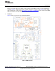
Schematics www.ti.com 6 Schematics A B C MSP430FR5969 LaunchPad Main MCU 1 TDO TMS TDI JTAG TCK TEST RST RST CTS_TARGETIN TX_TARGETOUT RX_TARGETIN 1 RTS_TARGETOUT APPLICATION_UART D JTAG VCC J4 J5 BP1-VCC 25 P2.1/TB0.0 BP7 26 P2.2/TB0.2 BP8 BP9 PJ.1/TDI13 PJ.3/TCK15 P4.0/A8 16 P4.1/A9 17 P4.3/A11 19 P4.2/A1018 PJ.2/TMS/ACLK14 BP6 P2.5/TB0.020 BP5 P2.6/TB0.121 BP4 TEST/SBWTCK22 BP18 P2.0/TB0.624 BP19 BP3 NMI/SBWTDIO/RST 23 BP16-RST PJ.
Schematics www.ti.com A C B D Main MCU - Debugger and Power Connections 1 1 External Power Supply J21 1 RX_TARGETIN 2 V_DEBUGGER V_EXT 3 2 3 TEST 1 4 RST J12 5 6 TX_TARGETOUT Measure Current J10 dnp Bypass V_EXT 1 eZ430 50mil header External Power Selection2 V_CHARGE R2 Debugger V_DEBUGGER 3 10 Place Jumper R7 Cap Selection VCC 1 VCC 1 Place Jumper J11 Current Limiter 3 + Charge Cap EZFET_SBWNC C7 J8 dnp EEC-S0HD104H 0.
Schematics www.ti.com A C B D eZ-FET - USB Interface and Power Supply eZ-FET Rev1.2 1 7 6 1 CONN_USB_ZX62R-B-5P 5 PGND 4 3 2 R104 27 EZFET_DP EZFET_PU.0/DP EZFET_DM EZFET_PU.
Schematics www.ti.com A C B D eZ-FET - Host MCU for emulation Q101 PIEZO_CSTCR4M00G15L992 EZFET_TEST PJ.0/TDO 60 TEST/SBWTCK 59 EZFET_VBUS EZFET_TDI EZFET_TDO PJ.1/TDI/TCLK 61 EZFET_TCK EZFET_TMS EZFET_RST PJ.3/TCK 63 R109 47k PJ.2/TMS 62 EZFET_VCC EZFET_PU.0/DP 1 EZFET_PU.1/DM 3 1 EZFET_PUR eZ-FET Rev1.2 C102 C107 220n 220n 1 EZFET_RST C112 1 P6.0/CB0/A0 2 R125 150k VSSU 49 PU.0/DP 50 PUR 51 VBUS 53 PU.1/DM 52 V18 55 VUSB 54 AVSS2 56 P5.2/XT2IN 57 P5.
Schematics www.ti.com A C B D eZ-FET - MCU controlled DCDC converter eZ-FET Rev1.2 1 1 EZFET_VCC + C106 C124 4.7u 100n AVSS 13 DVSS 14 AVCC 15 PWPD R112 220k DVCC 16 17 EZFET_VCCOUT EZFET_AVCCOUT 1 P1.0 2 P1.1 3k3 EZFET_DCDCPULSE 3 P1.2 2k2 EZFET_VCCOUT 6k8 TEST 10 EZFET_DCDCTEST 5 P1.7 EZFET_DCDCRST 2 8 P1.4 2 R117 4k7 EZFET_VCCOUT 4 P1.3MSP430G2452RSARST 9 EZFET_DCDCIO0 R114 220k R128 XOUT 11 MSP102 P1.5 33p R127 P1.
Revision History www.ti.com Revision History Changes from Original (February 2014) to A Revision .................................................................................................. Page • • • • • • • • • • • • • • • • • • • • • • • • • Changed title of document ............................................................................................................... 5 Changed contents of Section 1.1 to improve description and add links .................................................
IMPORTANT NOTICE Texas Instruments Incorporated and its subsidiaries (TI) reserve the right to make corrections, enhancements, improvements and other changes to its semiconductor products and services per JESD46, latest issue, and to discontinue any product or service per JESD48, latest issue. Buyers should obtain the latest relevant information before placing orders and should verify that such information is current and complete.