MSP-EXP430FR5739 FRAM Experimenter Board User's Guide Literature Number: SLAU343B May 2011 – Revised February 2012
SLAU343B – May 2011 – Revised February 2012 Submit Documentation Feedback Copyright © 2011–2012, Texas Instruments Incorporated
Contents 1 ................................. 5 ............................................................................................................... 5 1.2 Kit Contents .............................................................................................................. 6 1.3 MSP-EXP430FR5739 Board Overview ............................................................................... 6 1.4 Connecting the Hardware ..........................................................................
www.ti.com List of Figures 1 MSP-EXP430FR5739 Overview .......................................................................................... 5 2 Comparing Write Speeds When Writing to Nonvolatile Memory (MSP430FR5739 FRAM vs MSP430F2274 Flash) ...................................................................................................... 8 3 Comparing Average Power When Writing to Nonvolatile Memory at 13 kBps (MSP430FR5739 FRAM vs MSP430F2274 Flash) .......................................
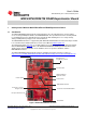
User's Guide SLAU343B – May 2011 – Revised February 2012 MSP-EXP430FR5739 FRAM Experimenter Board 1 Getting Started With the MSP-EXP430FR5739 FRAM Experimenter Board 1.1 Introduction The MSP-EXP430FR5739 Experimenter Board introduces TI's first embedded ferro-electric random access memory (FRAM) based MCU, the MSP430FR5739.
Getting Started With the MSP-EXP430FR5739 FRAM Experimenter Board 1.2 www.ti.com Kit Contents The MSP-EXP430FR5739 FRAM Experimenter Board kit includes the following: • The MSP-EXP430FR5739 board • Mini USB-B cable, 0.5 m • 12-pin PCB connectors (two male and two female) • 32.768-kHz clock crystal from Microcrystal (www.microcrystal.com) The 32.768-kHz crystal can be used as the low-frequency XT oscillator. It is not required for the User Experience code and can be populated as needed.
MSP-EXP430FR5739 User Experience Demo www.ti.com 2 MSP-EXP430FR5739 User Experience Demo 2.1 Associated Zip Folder Contents The zip file that contains the software and source code for the MSP-EXP430FR5739 can be downloaded from www.ti.com/lit/zip/slac492. The contents of the zip include: • User Experience source code and project files • Drivers that support the board installation • PC GUI The design files for the experimenter board are can be downloaded from www.ti.com/lit/zip/slac502. 2.
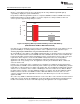
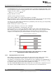
MSP-EXP430FR5739 User Experience Demo 2.2.2 www.ti.com Using Mode 1 – FRAM High Speed Writes Mode 1 is entered by pressing S1 once, followed by S2. On entry, LED8 through LED1 light up sequentially to display the speed of FRAM writes. Every time the LED1 through LED8 sequence is completed, 800KB are written to FRAM. In this mode, FRAM is bring written to at about 1.8MB per second. In comparison, a full-speed write to flash can achieve speeds of approximately 13kB per second.
MSP-EXP430FR5739 User Experience Demo www.ti.com 2.2.2.1 Measuring Current on the MSP-EXP430FR5739 While measuring the active power in a mode, the LEDs should be turned off and the UART transmissions should be halted. This is done by pressing switch S2 while inside the mode. Switch S2 toggles the display settings, turning them on or off as needed.
MSP-EXP430FR5739 User Experience Demo 2.2.3.1 www.ti.com The Math Behind Mode 2 The MSP430F2274 device was used as a benchmark device to calculate the maximum flash write speed. For a 512-byte block of flash, the following parameters were obtained from the MSP430F2274 data sheet: Segment erase time = 4819 × tFTG = 16 ms Where, tFTG = 1 / fFTG ≈ 1 / 300 kHz 512 bytes write time ≈ 51.2 ms Total time to write to 512 bytes ≈ 67.2 ms Time to write to 100KB = 6.72 seconds, which calculates to 14.
MSP-EXP430FR5739 User Experience Demo www.ti.com Using Mode 3 – Accelerometer Demo 2.2.4 Mode 3 is entered by pressing switch S1 three times, followed by switch S2. Upon entering this mode, the on-board accelerometer (see Figure 4) is calibrated. To aid this calibration process, it is recommended to place the board on a level surface before entering the mode. 3 Axis Accelerometer Figure 4. On-Board Accelerometer After the calibration sequence is completed, LED4 and LED5 are turned on.
MSP-EXP430FR5739 User Experience Demo www.ti.com Using Mode 4 – Temperature Sensor Demo 2.2.5 Mode 4 is entered by pressing switch S1 four times, followed by switch S2. Upon entering this mode, the on-board thermistor (see Figure 5) is calibrated. NTC Thermistor Figure 5. On-Board NTC Thermistor After the calibration sequence is completed, LED4 and LED5 are turned on. When the NTC resistor is heated (for example, by placing a finger on it), LED3 through LED1 are turned on sequentially.
MSP-EXP430FR5739 User Experience Demo www.ti.com 2.3 View, Edit, or Recompile the User Experience Code Using an IDE There are different development software tools available for the MSP-EXP430FR5739 board. IAR Embedded Workbench™ KickStart™ and Code Composer Studio™ (CCS) IDEs are both available in a free limited version. IAR Embedded Workbench allows 4KB of C-code compilation. CCS is limited to a code size of 16KB. The software is available at www.ti.com/msp430.
MSP-EXP430FR5739 Hardware www.ti.com 3 MSP-EXP430FR5739 Hardware 3.1 MSP430FR5739IRHA Device Pin Designation See the MSP430FR5739 data sheet (SLAS639) for the latest information. RHA PACKAGE (TOP VIEW) P2.4/TA1.0/UCA1CLK/A7*/CD11 P2.3/TA0.0/UCA1STE/A6*/CD10 P2.7 DVCC DVSS 31 32 33 35 34 36 37 39 30 1 2 29 MSP430FR5721 MSP430FR5723 MSP430FR5725 MSP430FR5727 MSP430FR5729 MSP430FR5731 MSP430FR5733 MSP430FR5735 MSP430FR5737 MSP430FR5739 3 4 5 6 7 8 9 28 27 26 25 24 23 22 10 PJ.
TP6 TP4 TP2 TP7 TP5 TP3 TP1 GND GND SLAU343B – May 2011 – Revised February 2012 Submit Documentation Feedback LED0 green GND R26 270 EZ_VCC 1u/6.3V C4 URTS UDTR UDSR UCTS 100n C5 1 2 3 4 5 6 7 8 9 10 11 12 13 14 15 16 C1 10n RESET R1 47k 16p C2 12MHz Q1 16p C3 EZ_VCC 64 63 62 61 60 59 58 57 56 55 54 53 52 51 50 49 48 47 46 45 44 43 42 41 40 39 38 37 36 35 34 33 R3 47k SCL SDA BRXDI BTXDI URXD UTXD RST3410 R2 47k GND 100R 100R 100R 100R J3 9 7 5 3 1 P2.
MSP-EXP430FR5739 FRAM Experimenter Board C8 R16 47k EZ_VCC Copyright © 2011–2012, Texas Instruments Incorporated R11 15k R25 1k5 R23 100R EZ_VCC UTXD URXD R17 DNP 47k R10 10k R24 1k5 SCL SDA CLK3410 BRXDI BTXDI DNP GND 1u/6.3V RST3410 EZ_VCC D1 1N4148 33k GND R22 3k3 3k3 R19 R12 X1 X2 4 3 2 1 SDA SCL P3.0 P3.1 P3.3 P3.
S1 J6 S2 2 GND .1u P3.2 C58 GND GND VCC Ext_PWR DNP C22 XINR 12pF DNP C21 XOUTR 12pF 10uF/10V C23 2 1 GND 2 1 2 3 4 5 6 7 8 DNP 2 or 3-Axis Accelerometer GND P3.3 16 15 14 13 12 11 10 9 P2.7 NC VS VS NC XOUT NC YOUT NC ADXL322/330 NC ST COM NC COM COM COM ZOUT 4.7u C53 R34 1 ACC .1u C15 R35 P1.4 GND PJ.0 PJ.1 GND . .1u 1u GND 7 C1 P3.1 P3.0 C16 P2.7 GND PJ.2 GND PJ.3 SV1 P4.0 P2.0 P1.
MSP-EXP430FR5739 Hardware 3.3 www.ti.com PCB Layout Figure 10.
MSP-EXP430FR5739 Hardware www.ti.com Figure 11.
MSP-EXP430FR5739 Hardware www.ti.com Figure 12.
MSP-EXP430FR5739 Hardware www.ti.com 3.4 Bill of Materials (BOM) Table 2 shows the bill of materials for the MSP-EXP430FR5739 board. Table 2. Bill of Materials (BOM) Ref Des Numbe r per Board 1 C1 1 10n 2 C2,C3 2 16p 3 C4, C6, C8 3 1u/6.3V 4 C5, C7, C11, C12,C13 5 100n 5 C15, C16, C17, C18, C20, C31, C58 7 100n 6 C9, C10 2 22p 7 C14 1 470n 8 C19 1 10u Pos. Description 9 C21, C22 0 12pF 10 C23 1 10uF/10V 11 C24 1 2.2nF 12 C32, C53 2 4.
Suggested Reading www.ti.com Table 2. Bill of Materials (BOM) (continued) 4 Pos.
IMPORTANT NOTICE Texas Instruments Incorporated and its subsidiaries (TI) reserve the right to make corrections, modifications, enhancements, improvements, and other changes to its products and services at any time and to discontinue any product or service without notice. Customers should obtain the latest relevant information before placing orders and should verify that such information is current and complete.