
Datasheet


MF10-N
www.ti.com
SNOS547C –JUNE 1999–REVISED APRIL 2013
(17)
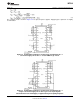
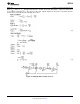
The complete circuit is shown in Figure 32 for split ±5V power supplies. Supply bypass capacitors are highly
recommended.
Figure 32. Fourth-Order Chebyshev Low-Pass Filter from Example in 3.1.
±5V Power Supply. 0V–5V TTL or −5V ±5V CMOS Logic Levels.
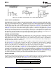
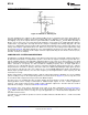
Figure 33. Fourth-Order Chebyshev Low-Pass Filter from Example in 3.1.
Single +10V Power Supply. 0V–5V TTL Logic Levels. Input Signals
Should be Referred to Half-Supply or Applied through a Coupling Capacitor.
Copyright © 1999–2013, Texas Instruments Incorporated Submit Documentation Feedback 23
Product Folder Links: MF10-N